
Intel Pentium 4 Processor 478-Pin Socket (mPGA478) Design Guidelines


Intel® Pentium® 4 Processor 478-Pin Socket (mPGA478)
R
30
ground
no connect &
no pin
Rsa R1 R2
R4 R1a
Rs R1b R1c
signal
Probe Pad
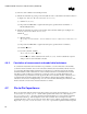
Figure 4-11. Capacitance Measurement Configuration
Configuration R1
Figure 4-12. Capacitance Fixture Design and Measurement Configuration
4.7.1. Procedure for Capacitance Measurements:
Measurement equipment and steps in this section are the same as the procedure for inductance measurements
in section 0 through step d. The following procedure must be completed after that point.
Measurement Steps:
(a) Measure the capacitance of the test vehicle mounted on the socket (Figure 4-9 – Top view of the Test
vehicle
) for the Configuration R1. Call this Csocket_assembly. Export data into the MDS/ADS or
(capture data at frequency specified in item 6 of Table 4-1 –
Electrical Requirements).
(b) Measure the capacitance of the test vehicle with the pins cut (Figure 4-9 –
Top view of the Test vehicle)
for the configuration R1. Call this Ctest_vehicle. Measure 30 units. The test vehicle for 30 units must
be chosen from different lots. Use 5 different lots, 6 units from each lot. Export data into MDS/ADS or
(capture data at frequency specified in item 6 of Table 4-1 –
Electrical Requirements).
(c) For each socket unit, calculate
Csocket = Csocket_assembly – Ctest_vehicle
Ctest_vehicle will be subtracted from each Csocket_assembly and the result will be compared with the
spec value for each individual socket unit.