
Intel Pentium 4 Processor 478-Pin Socket (mPGA478) Design Guidelines

Intel® Pentium® 4 Processor 478-Pin Socket (mPGA478)
R
7
2. Assembled Component and Package
Description
Information provided in this section is to ensure dimensional compatibility of the socket and actuation
mechanism with the integrated package assembly. Zero insertion force will be required for placement of the
mPGA478 package into the socket prior to actuation.
2.1. Assembled Component Description
The assembled component may consist of a heatsink, EMI, Clips, Fan, RM (retention mechanism), and
processor. Specific details can be obtained from the Intel
®
Pentium
®
4 Processor in 478-Pin Package
Thermal Design Guidelines, consult your Intel field representative to obtain this document. The heatsink will
be statically loaded onto the package after the package is mated with the socket and actuated. For mechanical
details refer to Section 3 –Mechanical Requirements.
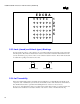
2.2. Package Description
The outline of the package that can be used with mPGA478 Socket is illustrated in Section 7 – Appendix Z.1.
It will contain a 26 x 26 array of pins (with a center cavity gap of a 14 x14 array of pins) contained in a
substrate that is 36.5 mm x 36.5 mm maximum. The pin length is 2.03 mm nominal.