
Intel Pentium 4 Processor CK00 Clock Synthesizer/Driver Design Guidelines

CK00 Clock Synthesizer/Driver Design Guidelines
Page 12
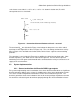
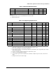
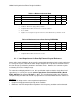
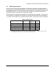
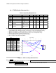
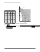
Figure 2.4 – Illustration of Series Isolation Resistance Rs
The series resistors R
S
have the tradeoff of reducing the amount of voltage headroom available
to the current driving circuit. For the principal Voh configuration of Voh=0.7V, the voltage at the
output of the buffer will be in the range of 1.1V and be similar to the voltage at the reference
resistor R
Ref
. For configurations with Voh greater then 0.7V, it is assumed that R
S
will be
decreased such that the voltage present at the pin output will not exceed 1.2V neglecting
overshoot. Such a decrease in R
S
may result in reflections from the on-die capacitance which,
depending on system implementation can cause additional reflection and ringback. The system
designer should simulate this effect using realistic die and package capacitance models. The
designer should also be aware that there is a trace length dependency on the effect of the
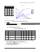
reflections. To illustrate the effect of decreasing R
S
below 33 Ohms in one example system,
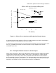
the plot shown in Figure 2.5 has been included. Figure 2.5 applies only to a specific source-
terminated case with no load termination and cannot be used to make predictions of other
systems. Furthermore, the plot applies only to a discrete length of clock trace. In the specific
example, it is apparent that if R
S
were reduced from 33 Ohms to 15 Ohms, this could cause an
increase in overshoot of approximately 0.05V at the trace length simulated.
R=Zo
R=Zo
C_die + Cpkg
= 1 - 6 pF
Rs = ~ 33
Rs = ~ 33
Series Isolation Resistor