
Intel Pentium 4 Processor CK00 Clock Synthesizer/Driver Design Guidelines

CK00 Clock Synthesizer/Driver Design Guidelines
Page 27
4.1.2 Multiple PLL Jitter Tracking Specification.
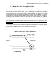
The clock driver’s closed loop jitter bandwidth must be set low to allow any PLL-based device to
track the jitter created by the clock driver. This 1:1 relationship is critical when the clock driver
drives two or more PLLs. A worst-case timing issue would occur if one PLL attenuated the jitter
and another device (PLL or non-PLL) tracked the jitter completely. To reduce the possibility of
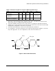
this we require that the -20dB attenuation point be less than or equal to 500KHz. Most clock
vendors do not specify their jitter bandwidth characteristics or specify it only at the -3dB level.
To allow for greatest flexibility in loop design we require the vendor to provide the -20dB point.
This specification may be guaranteed by design and/or measured with a spectrum analyzer.
This specification is intended to replace or clarify the Pentium
®
processor specification, which
was stated as:
“To ensure a 1:1 jitter frequency relationship between the amplitude of the input jitter and the
internal and external clocks, the jitter frequency spectrum should not have any power spectrum
peaking between 500 kHz and 1/3 of the clock operating frequency.”
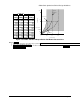
Gain
Frequency
-3dB
-20dB
500 Khz
About
50 Khz
0dB
Ideal Closed Loop Jitter Bandwidth
-20 dB/Decade
SPEC
(Not to Scale)
Peak is < 500Khz