
Intel Pentium 4 Processor CK00 Clock Synthesizer/Driver Design Guidelines

CK00 Clock Synthesizer/Driver Design Guidelines
Page 29
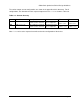
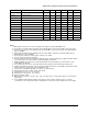
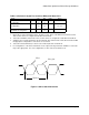
Table 5.3 Resistive Lumped Test Loads for Differential Host Clock
Clock Rs Rp Units Notes
Host Clocks – 60 ohm
configuration
33.2
1%
61.9
1%
Ohms 2, 3, 5
Host Clocks – 50 ohm
configuration
33.2
1%
49.9
1%
Ohms
1, 2, 3, 5
Host Clocks – Double
Terminated configuration
0 24.9
1%
Ohms 4
1. Expected test load configuration unless otherwise noted. This is a 50 Ohm environment test load.
This assumes device is configured for 50 Ohm environment.
2. Test load for 60 Ohm environment. This assumes device is configured for a 60 Ohm environment.
3. Suppliers must correlate parameters measured in 50 ohm environment to a 60 ohm environment with
the appropriate configurations of the device for each load.
4. Test load for dual terminated (i.e. both source and load) 50 ohm environment.
5. For configurations of the device intended to create output current greater then 14mA these test loads
may not be appropriate. For such configurations, a value of Rs=0 should be used.
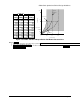
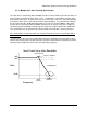
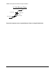
Figure 5.3 CK133 Clock Waveforms
Host
Host_bar
Tperiod