
Intel Pentium 4 Processor CK00 Clock Synthesizer/Driver Design Guidelines


CK00 Clock Synthesizer/Driver Design Guidelines
Page 9
2. Example Circuits
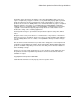
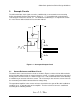
The differential Host clock signals are to be established by a current mode current steering
buffer conceptually similar to that shown in Figure 2.1. I
Out
is established by a mirrored and
scaled copy of a reference current, I
Ref
. The method of establishing I
Ref
is explained in Section
2.1 in the manner believed to be the best known method.
Figure 2.1 – Conceptual Output Circuit
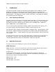
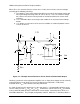
2.1 Current Reference and Mirror Circuit
The details of the current reference circuit are shown in Figure 2.2 in the fashion believed to be
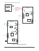
the best known method using an external reference resistor. A simple current mirror connected
directly to the external resistor, as shown in Figure 2.3, is not recommended due to the difficulty
of establishing an accurate reference current. This inaccuracy in the reference current is due to
the uncertainty of the diode-connected device voltage drop.
The operational amplifier in the current reference circuit drives the gate of M
Iref
with feedback to
establish V
Ref
=1.1V at both inputs of the amplifier. Thus the reference current is established
according to the following formula:
I
Ref
= 1.1 / R
Ref
Iout
R=Zo
R=Zo
Internal External
3.3V