
Intel Pentium 4 Processor Extreme Edition on 0.13 Micron Process in the 775-Land Package Datasheet

16 Datasheet
Electrical Specifications
2.3.1 V
CC
Decoupling
Regulator solutions need to provide bulk capacitance with a low Effective Series Resistance (ESR)
and keep a low interconnect resistance from the regulator to the socket. Bulk decoupling for the
large current swings when the part is powering on, or entering/exiting low power states, must be
provided by the voltage regulator solution (VR). In addition, a sufficient quality of low ESR
ceramic capacitors are required in the socket cavity to ensure proper high frequency noise
suppression. For more details on this topic, contact your Intel representative for further
documentation and the Voltage Regulator-Down (VRD) 10.1 Design Guide for Desktop and
Transportable Socket 775.
2.3.2 FSB GTL+ Decoupling
The Pentium 4 processor Extreme Edition in the 775-land package integrates signal termination on
the die as well as incorporating high frequency decoupling capacitance on the processor package.
Decoupling must also be provided by the system baseboard for proper GTL+ bus operation. For
more information and documentation, contact your Intel representative.
2.4 Voltage Identification
The VID specification for the Pentium 4 processor Extreme Edition in the 775-land package is
supported by the Voltage Regulator-Down (VRD) 10.1 Design Guide for Desktop and
Transportable Socket 775. The voltage set by the VID signals is the reference VR output voltage to
be delivered to the processor VCC pins. The specifications have been set such that one voltage
regulator can work with all supported frequencies.
Individual processor VID values may be calibrated during manufacturing such that two devices at
the same speed may have different VID settings.
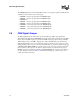
The Pentium 4 processor Extreme Edition in the 775-land package uses six voltage identification
signals, VID[5:0], to support automatic selection of power supply voltages. Table 2-1 specifies the
voltage level corresponding to the state of VID[5:0]. A ‘1’ in this table refers to a high voltage level
and a ‘0’ refers to low voltage level. If the processor socket is empty (VID[5:0] = 111111), or the
voltage regulation circuit cannot supply the voltage that is requested, it must disable itself. See the
Voltage Regulator-Down (VRD) 10.1 Design Guide for Desktop and Transportable Socket 775 for
more details.
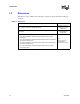
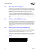
Table 2-1. Voltage Identification Definition
VID5 VID4 VID3 VID2 VID1 VID0 VID
101101 1.5250
101100 1.5500
101011 1.5750
101010 1.6000