
Intel Pentium 4 Processor Extreme Edition on 0.13 Micron Process in the 775-Land Package Datasheet

24 Datasheet
Electrical Specifications
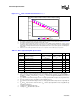
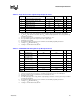
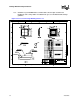
Figure 2-1. V
CC
Static and Transient Tolerance
1, 2, 3, 4
NOTES:
1. The loadline specification includes both static and transient limits except for overshoot allowed as shown in Section 2.12.
2. This loadline specification shows the deviation from the VID set point.
3. The loadlines specify voltage limits at the die measured at the VCC_SENSE and VSS_SENSE lands. Voltage regulation
feedback for voltage regulator circuits must be taken from processor VCC and VSS lands. Refer to the Voltage Regulator-
Down (VRD) 10.1 Design Guide for Desktop and Transportable Socket 775 for socket loadline guidelines and VR implemen-
tation details.
4. Adherence to this loadline specification for the processor is required to ensure reliable processor operation.
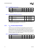
Table 2-7. GTL+ Signal Group DC Specifications
Symbol Parameter Min Max Unit Notes
1
NOTES:
1. Unless otherwise noted, all specifications in this table apply to all processor frequencies and voltages.
GTLREF0 Reference Voltage
(0.0986V
CC
+
0.6106V
TT
) – 10.21%
(0.0986V
CC
+
0.6106V
TT
) + 4.6%
V
2
2. This is the measured value after the processor is plugged into the platform. The typical GTLREF0 of
(0.0986V
CC
+0.6106V
TT
) is based on V
TT
of 1.2 V, V
CC
of 1.575 V, and typical GTLREF0 resistor values on
the platform.
V
IH
Input High Voltage 1.10*GTLREF0 V
CC
V
3,4
3. V
IL
is defined as the maximum voltage level at a receiving agent that will be interpreted as a logical low value.
4. The V
CC
referred to in these specifications is the instantaneous V
CC
.
V
IL
Input Low Voltage 0.0 0.9*GTLREF0 V
4,5,6
5. V
IH
is defined as the minimum voltage level at a receiving agent that will be interpreted as a logical high val-
ue.
6. V
IH
and V
OH
may experience excursions above V
CC
. However, input signal drivers must comply with the sig-
nal quality specifications.
V
OH
Output High Voltage N/A V
CC
V
4
I
OL
Output Low Current N/A 50 mA —
I
HI
Land Leakage High N/A 100 µA
7
7. Leakage to V
SS
with land held at V
CC
.
I
LO
Land Leakage Low N/A 500 µA
8
8. Leakage to V
CC
with land held at 300 mV.
R
ON
Buffer On Resistance 8.4 13.2 Ω
-0.250 V
-0.200 V
-0.150 V
-0.100 V
-0.050 V
0.000 V
0 A 20 A 40 A 60 A 80 A 100 A 120 A
Vccmax Vcctyp Vccmin