
Intel Pentium 4 Processor Extreme Edition on 0.13 Micron Process in the 775-Land Package Datasheet

Datasheet 27
Electrical Specifications
NOTES:
1. V
OS
is measured overshoot voltage.
2. T
OS
is measured time duration above VID.
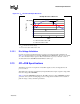
2.12.1 Die Voltage Validation
Overshoot events from application testing on real processors must meet the specifications in
Table 2-12 when measured across the VCC_SENSE and VSS_SENSE lands. Overshoot events that
are < 10 ns in duration may be ignored. These measurements of processor die level overshoot
should be taken with a 100 MHz bandwidth limited oscilloscope.
2.13 GTL+FSB Specifications
Termination resistors are not required for most GTL+ signals, as these are integrated into the
processor silicon.
Valid high and low levels are determined by the input buffers that compare a signal’s voltage with a
reference voltage called GTLREF0.
Table 2-13 lists the GTLREF0 specifications. The GTL+ reference voltage (GTLREF0) should be
generated on the system board using high precision voltage divider circuits. For more details on
platform design, contact your Intel representative.
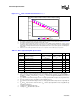
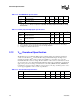
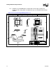
Figure 2-2. V
CC
Overshoot Example Waveform
Time
Example Overshoot Waveform
Voltage (V)
VID
VID + 0.050
T
OS
V
OS
T
OS
: Overshoot time above VID
V
OS
: Overshoot above VID