
Intel Pentium 4 Processor Extreme Edition on 0.13 Micron Process in the 775-Land Package Datasheet

28 Datasheet
Electrical Specifications
§
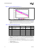
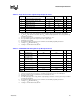
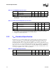
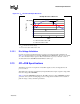
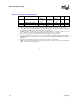
Table 2-13. GTL+ Bus Voltage Definitions
Symbol Parameter Min Typ Max Units Notes
1
NOTES:
1. Unless otherwise noted, all specifications in this table apply to all processor frequencies and voltages.
GTLREF0 Bus Reference Voltage
(0.0986V
CC
+
0.6106V
TT
) –
10.21%
(0.0986V
CC
+0.6106V
TT
)
(0.0986V
CC
+
0.6106V
TT
) +
4.6%
V
2,3,4,5
2. The tolerances for this specification have been stated generically to enable the system designer to calculate
the minimum and maximum values across the range of V
CC
and V
TT
.
3. GTLREF0 should be generated from V
CC
and V
TT
by a voltage divider of 1% tolerance resistors or 1% tol-
erance, matched resistors. For implementation details, contact your Intel representative.
4. The V
CC
and V
TT
referred to in these specifications is the instantaneous V
CC
and V
TT
.
5. This is the measured value after the processor is plugged into the platform. The Typical GTLREF0 of
(0.0986V
CC
+0.6106V
TT
) is based on V
TT
of 1.2 V, V
CC
of 1.575 V, and typical GTLREF0 resistor values on
the platform.
R
TT
Termination Resistance 54 60 66 Ω
6
6. R
TT
is the on-die termination resistance measured at V
OL
of the GTL+ output driver.
COMP[1:0] COMP Resistance 59.8 60.4 61 Ω
7
7. COMP resistance must be provided on the system board with 1% tolerance resistors. For implementation
details, contact your Intel representative.