
Intel Pentium 4 Processor Extreme Edition on 0.13 Micron Process in the 775-Land Package Datasheet

Datasheet 33
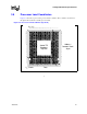
Package Mechanical Specifications
3.3 Package Loading Specifications
Table 3-1 provides dynamic and static load specifications for the processor package. These
mechanical maximum load limits should not be exceeded during heatsink assembly, shipping
conditions, or standard use condition. Also, any mechanical system or component testing should
not exceed the maximum limits. The processor package substrate should not be used as a
mechanical reference or load-bearing surface for thermal and mechanical solution. The minimum
loading specification must be maintained by any thermal and mechanical solutions.
.
3.4 Package Handling Guidelines
Table 3-2 includes a list of guidelines on package handling in terms of recommended maximum
loading on the processor IHS relative to a fixed substrate. These package handling loads may be
experienced during heatsink removal.
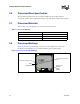
3.5 Package Insertion Specifications
The Pentium 4 processor Extreme Edition in the 775-land package can be inserted into and
removed from a LGA775 socket 15 times. The socket should meet the LGA775 requirements. For
more details contact your Intel representative.
Table 3-1. Processor Loading Specifications
Parameter Minimum Maximum Notes
Static 18 lbf 70 lbf
1, 2, 3
NOTES:
1. These specifications apply to uniform compressive loading in a direction normal to the processor IHS.
2. This is the maximum force that can be applied by a heatsink retention clip. The clip must also provide the
minimum specified load on the processor package.
3. These specifications are based on limited testing for design characterization. Loading limits are for the
package only and does not include the limits of the processor socket.
Dynamic — 170 lbf
1, 3, 4
4. Dynamic loading is defined as the sum of the load on the package, from a 1 lb heatsink mass accelerating
through an 11 ms trapezoidal pulse of 50 g, and the maximum static load.
Table 3-2. Package Handling Guidelines
Parameter Maximum Recommended Notes
Shear 70 lbf
1, 4
NOTES:
1. A shear load is defined as a load applied to the IHS in a direction parallel to the IHS top surface.
Tensile 25 lbf
2, 4
2. A tensile load is defined as a pulling load applied to the IHS in a direction normal to the IHS surface.
Torque 35 lbf-in
3, 4
3. A torque load is defined as a twisting load applied to the IHS in an axis of rotation normal to the IHS top
surface.
4. These guidelines are based on limited testing for design characterization.