
Intel Pentium 4 Processor Extreme Edition on 0.13 Micron Process in the 775-Land Package Datasheet


82 Datasheet
Boxed Processor Specifications
7.1.2 Boxed Processor Fan Heatsink Weight
The boxed processor fan heatsink will not weigh more than 450 grams. Refer to Chapter 5 and the
Intel
®
Pentium
®
4 Processor Extreme Edition on 0.13 Micron Process in the 775-land package
Thermal Design Guide for details on the processor weight and heatsink requirements.
7.1.3 Boxed Processor Retention Mechanism and Heatsink
Attach Clip Assembly
The boxed processor thermal solution requires a heatsink attach clip assembly to secure the
processor and fan heatsink in the baseboard socket. The boxed processor will ship with the heatsink
attach clip assembly.
7.2 Electrical Requirements
7.2.1 Fan Heatsink Power Supply
The boxed processor's fan heatsink requires a +12 V power supply. An attached fan power cable
will be shipped with the boxed processor to draw power from a power header on the baseboard.
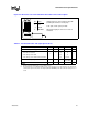
The power cable connector and pinout are shown in Figure 7-5. Baseboards must provide a
matched power header to support the boxed processor. Table 7-1contains specifications for the
input and output signals at the fan heatsink connector.
The fan heatsink outputs a SENSE signal that is an open- collector output that pulses at a rate of
2 pulses per fan revolution. A baseboard pull-up resistor provides V
OH
to match the system board-
mounted fan speed monitor requirements, if applicable. Use of the SENSE signal is optional. If the
SENSE signal is not used, pin 3 of the connector should be tied to GND.
The Pentium 4 processor Extreme Edition manufactured on the 0.13 micron process technology
does not support T-diode based fan speed control hence the 4th pin (labeled CONTROL) of the fan
connector for this processor is null. (The fan speed will be controlled by the integrated fan
controller)
Note: The boxed processor’s fan heatsink requires a constant +12 V supplied to pin 2 and does not
support variable voltage control or 3-pin PWM control.
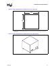
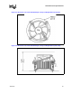
The power header on the baseboard must be positioned to allow the fan heatsink power cable to
reach it. The power header identification and location should be documented in the platform
documentation, or on the system board itself. Figure 7-6 shows the location of the fan power
connector relative to the processor socket. The baseboard power header should be positioned
within 4.33 inches from the center of the processor socket.