
Intel Pentium 4 Processor in the 423-pin package EMI Guideline

Intel® Pentium® 4 Processor in the 423-pin package EMI Guideline
3
®
1.0
Introduction
As microprocessor amperage and speeds increase, the ability to contain the corresponding
electromagnetic radiation becomes more difficult. Frequencies generated by the Pentium ® 4
processor will be in the low gigahertz (GHz) range, which will impact both the system design and the
electromagnetic interference (EMI) test methodology.
This document is intended to provide electrical and mechanical design engineers with information in
regards to developing a Pentium® 4 processor based system to meet government EMI regulations.
Heat sink grounding, processor shielding, differential and spread spectrum clocking and the test
methodology impact to FCC Class B requirements are discussed.
Designers should be aware that implementing all the recommendations in this guideline will not
guarantee compliance to EMI regulations. Rather, these guidelines may help to reduce the emissions
from processors and motherboards and make chassis design easier.
1.1
Terminology
Electromagnetic Interference (EMI)
- electromagnetic radiation from an electrical source that
interrupts the normal function of an electronic device.
Electromagnetic Compatibility (EMC) -
the successful operation of electronic equipment in its
intended electromagnetic environment.
1.2
References
Intel Pentium 4 Processor and 850 Chipset Platform Design Guide.
Intel Pentium 4 Processor in the 423-Pin Package Datasheet.
Intel Pentium 4 Processor Thermal Design Guidelines.
`CK00 Clock Synthesizer Design Guidelines.
1.3
Brief EMI Theory
Electromagnetic energy transfer can be viewed in four ways: radiated emissions, radiated
susceptibility, conducted emissions and conducted susceptibility. For PC system designers, reduction
of radiated and conducted emissions is the way to achieve EMC compliance. Susceptibility is typically
not a major concern in the desktop PC environment although it may be more important in an industrial
environment.
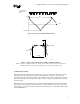
The main component of EMI is a radiated electromagnetic wave, which consists of both electric (E-
fields) and magnetic (H-fields) waves traveling together and oriented perpendicular to each other.
Although E and H fields are intimately tied together, they are generated by different sources. E-fields
are created by voltage potentials while H-fields are created by current flow. In a steady state
environment (where voltage or current is unchanging), E and H fields are also static and of no concern
to EMI. Changing voltages and currents are of concern since they contribute to EMI. If a dynamic E-
field is present then there must be a corresponding dynamic H-field, and vice versa. Motherboards
with fast processors will generate high frequency E and H fields from currents and voltages present in
the component silicon and signal traces.
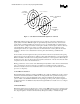
Two methods exist for minimizing E and H field emissions from a system: prevention and
containment. Prevention is achieved by implementing design techniques that minimize the ability of
the motherboard to generate EMI fields. Containment is used in a chassis environment to contain
radiated energy within the chassis. Careful consideration of board layout, trace routing and grounding
may significantly reduce the motherboards radiated emissions and make the chassis design easier.