
Intel Pentium 4 Processor in the 423-pin package EMI Guideline


Intel® Pentium® 4 Processor in the 423-pin package EMI Guideline
7
®
frequency signals. Designers will have to experimentally investigate the behavior of a particular
heatsink to determine its EMC performance.
Grounding of the heatsink through the Intel processor package is not possible with the current package
implementation but may be an option at some time in the future. As such, OEMs must design their own
heatsink grounding solution.
When designing a grounding mechanism for the heatsink care must be taken to minimize the
impedance and distance between the ground paths. Typical guidelines suggest ground points should be
separated by less than ¼ wavelength of the 3
rd
harmonic of the processor core frequency.
Grounding materials should be selected to eliminate galvanic action between the various metals with
which they will be in contact. Oxidation of the various materials should also be considered as some
oxides are non-conductive (for example, aluminum oxide) and will degrade EMC performance over
time. Manufacturing process residue or coatings to prevent oxidation should also be checked for
conductivity, especially at high frequencies.
2.5
Faraday Cages
Grounding of heatsinks may reduce EMI, but that alone may not be sufficient to pass the required tests.
Additional shielding of the processor itself may be necessary. A faraday cage placed around the
processor may provide a reduction in radiated noise and make chassis design easier.
A true faraday cage would completely surround the source of radiation and contain all radiated energy.
Within the limitations of processor packaging and motherboard assembly it is not possible to create a
true faraday cage around the processor. By using the heatsink and motherboard ground plane as two
sides of the cage and a metal frame to enclose the remaining four sides, a reasonable approximation of
a faraday cage can be achieved.
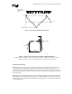
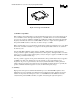
Intel has designed a ‘picture frame’ type of grounding device that fits between the processor and
heatsink, Figure 4. With this implementation, it is unnecessary to design a separate heatsink grounding
mechanism as the frame will provide this capability. OEMs who choose to use the Intel designed
grounding frame will need to provide ground pads on the top layer of the motherboard around the
processor socket. These pads will provide the necessary ground continuity to complete the faraday
cage. Exact physical dimensions of the frame, materials used and the required motherboard ground pad
descriptions are provided in the Mechanical Assembly and Design Guidelines listed above.
Investigations on a variety of Pentium® 4 processor motherboards indicates a ground frame is not
necessary to meet FCC or CISPR regulations. Based on this data, the ground frame depicted in Figure
4 will remain at the prototype stage, although further development may take place if greater EMI
containment is needed. It may be wise for motherboard designers to implement the ground pads
mentioned in the previous paragraph, in the event the ground frame does become necessary. Intel will
make every effort to assist OEMs who are interested in developing the faraday cage for their particular
application, but it should be noted that each OEM is ultimately responsible for ensuring their systems
meet the EMC regulations.