
Intel Pentium 4 Processor In the 423-pin Package Thermal Design Guidelines


Pentium® 4 processor in the 423-pin package Thermal Design Guidelines
10
5 DESIGNING FOR THERMAL PERFORMANCE
In designing for thermal performance, the goal is to keep the processor within the operational thermal specifications.
Failure to do so will shorten the life of the processor and potentially cause erratic system behavior. The thermal
design is required to ensure these operational thermal specifications are maintained. The heat generated by
components within the chassis must be removed to provide an adequate operating environment for both the
processor and other system components. Moving air through the chassis transports the heat generated by the
processor and other system components out of the system, while bringing in air from the external ambient
environment.
5.1 Airflow Management
It is important to manage the amount of air that flows within the system, as well as how it flows, to maximize the
amount of cool air that flows over the processor. System airflow can be increased by adding one or more fans to the
system, or by increasing the output (increasing the speed or size) of an existing system fan(s). Managing the airflow
direction using baffles or ducts can also increase local airflow. Heating effects from chipset, voltage regulators, add-
in boards, memory, and disk drives greatly reduce the cooling efficiency of this air, as does re-circulation of warm
interior air through the system fan. Care must be taken to minimize the heating effects of other system components,
and to eliminate warm air re-circulation.
If no air path exists across the processor, the warm air from the processor will not be removed from the system,
resulting in localized heating ("hot spots") around the processor. Heat sink fins passive thermal solution designs
should be aligned with the direction of airflow. If the airflow is horizontal the fins should be oriented horizontally.
Similarly, for a vertical airflow, the heat sink fins should be oriented vertically.
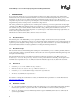
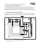
Figure 2 shows two examples of air exchange through a PC style chassis. The system on the left is an example of
good air exchange incorporating both the power supply fan as well as an additional system fan. The system on the
right shows a poorly vented system using only the power supply fan to move the air, resulting in inadequate airflow.
Drive Bays Drive Bays
Vents
Vents
V
ents
Power
Supply
Power
Supply
Fan Fan
Good CPU Airflow
Poor CPU Airflow
IO Cards
Good Venting = Good Air Exchange Poor Venting = Poor Air Exchange
FAN
Proc.
Proc.
IO Cards
000967
Figure 2. Example of Air Exchange through a PC Chassis
5.2 Bypass
Bypass is the distance around the heat sink where air may travel without passing through the fins of the heat sink. A
heat sink will have infinite bypass if it is sitting in free space. A heat sink which has a duct or other devices
surrounding it which are 0.2” (5.1mm) away from the outer edges of the heat sink has a bypass of 0.2” (5.1mm). A
smaller bypass forces more air to pass through the fins of the heat sink, rather than around the heat sink. This is
especially important as the heat sink fin density increases. The higher the fin density, the more resistance the heat