
Intel Pentium 4 Processor In the 423-pin Package Thermal Design Guidelines

Pentium® 4 processor in the 423-pin package Thermal Design Guidelines
11
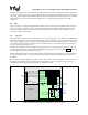
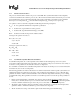
sink poses to the air and the more likely the air will travel around the heat sink instead of through it unless the
bypass is small. Air traveling around the heat sink, rather than through, will have little affect on cooling the
processor.
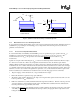
5.3 Heat Sink Solutions
One method of improving thermal performance is to increase the surface area of a device by attaching a metallic
heat sink. To maximize the heat transfer, the thermal resistance from the heat sink to the air can be reduced by
maximizing the airflow through the heat sink fins as well as by maximizing the surface area of the heat sink itself.
5.4 Pentium 4 processor Reference Heat Sink
Intel is enabling a reference heat sink for the Pentium® 4 processor. This active heat sink design includes a 60 mm
fan and is designed assuming a T
LA
of 45ºC and sufficient cross flow to maintain the local ambient temperature.
In order to maximize longevity, a heat sink consisting of folded aluminum fins brazed to a copper base has been
designed. The copper base provides increased heat spreading and the folded fins provide greater surface area for
thermal dissipation.
5.4.1 Heat Sink Weight
The heat sink attachment requires a retention mechanism. Heat sinks that attach to the reference retention
mechanism should not exceed 450 grams. These are the design limits for the motherboard components, heat sink
retention mechanism, heat sink attach clips, and 423 pin socket to withstand mechanical shock and vibration.
The test limits for vibration are 10min/axis, 3 axes over a frequency range of 5Hz to 500Hz. This results
in a Power
Spectral Density (PSD) of 3.13g RMS. The system level shock design limits are 30G trapezoidal, 11 ms duration,
170 in./sec minimum velocity change applied 3 times in the + and – directions in each of 3 perpendicular axes.
5.4.2 Altitude
The reference heat sink solutions will be evaluated at sea level. In general the performance drops by about 0.5-1.0 ºC
per 1000 feet of elevation. The system designer needs to account for this in the overall system thermal design.
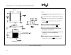
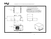
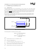
5.4.3 Heat Sink Mechanical Envelope
The following two figures show the critical to function (CTF) and maximum heat sink dimensions for the reference
heat sink design intended for the reference retention mechanism. Figure 3 shows the dimension and “keep-in” for
the heat sink base, while Figure 4 shows the maximum heat sink dimensions.