
Intel Pentium 4 Processor In the 423-pin Package Thermal Design Guidelines

Pentium® 4 processor in the 423-pin package Thermal Design Guidelines
16
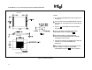
5.6.2 Direction
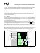
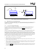
For passive cooling solutions, if the fan(s) is (are) not moving air through the heat sink, then little cooling can occur
and the processor may operate above the specified temperature. Two possibilities exist for blowing air through the
heat sink of a Pentium® 4 processor. Air can be blown horizontally, parallel to the baseboard, which blows the air
through the length of the heat sink. Alternatively the air stream can be blown vertically, perpendicular to the
baseboard, or down into the heat sink. This will depend on the layout of other components on the board and/or
within the chassis. Preferably the intake fan will blow through the heat sink lengthwise. In this case, it may be
possible for the heat sink fins to be shorter (z – axis). Both of these factors are considerations when laying out
components on the board and in the chassis.
The direction of the chassis airflow can be modified with baffles or ducts to direct the airflow toward the processor.
This will increase the local flow through the processor heat sink and may eliminate the need for a second, larger, or
higher speed fan. Baffles and ducts can also provide air to the heat sink without the preheating caused by other
system components
5.6.3 Size And Quantity
It does not necessarily hold true that the larger the fan the more air it blows. A small blower or axial fan using
ducting might direct more air through the heat sink than a large axial fan blowing non-directed air toward the heat
sink. The following provide some guidelines for size and quantity of the fan(s).
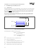
The system fan should be a minimum of 80 mm (3.150") square, with a minimum airflow of approximately
200 LFM (linear feet per minute). Ideally two (2) fans should be used. The intake air fan would blow cool air
directly toward the processor and heat sink assembly, while a second fan, possibly in the power supply would
exhaust the hot air out of the system.
5.6.4 Venting
Intake venting should be placed at the front (user side) of the system to avoid any re-circulation that can occur from
the rear of a system with little wall clearance. Location should be selected with consideration for cooling of
processor and peripherals (drives and add-in cards). Intake venting directly in front of the intake fan is the most
optimal location. The ideal design will provide airflow directly through the processor heat sink.
5.6.4.1 Placement
Exhaust venting in conjunction with the power supply exhaust fan is usually sufficient for smaller systems.
However, depending on the number, location and types of add-in cards, exhaust venting may be necessary near the
adapter cards. This should be modeled or prototyped for the optimum thermal potential. Hence, a system should be
modeled for the worst case; i.e. all expansion slots should be occupied with add-in options.
5.6.4.2 Area and/or Size
The area and/or size of the intake vents should consider the size and shape of the fan(s). Adequate air volume must
be obtained and thus will require adequate sized vents. Intake vents should be located in front of the intake fan(s)
and adjacent to the drive bays. Venting should be approximately 50% to 60% open in the EMI (Electro-Magnetic
Interference) containment area. Outside the EMI (Electro-magnetic Interference) containment area, the open
percentage can be greater if needed for aesthetic appeal (i.e., bezel/cosmetics). Caution should be exercised that
venting is not excessive or poorly placed which can cause re-circulation of warm exhaust air.
5.6.4.3 Vent Shape
Round, staggered pattern openings are best for EMI containment, acoustics and airflow balance.