
Intel Pentium 4 Processor In the 423-pin Package Thermal Design Guidelines

Pentium® 4 Processor in the 423-pin Package Thermal Design Guidelines
19
7.1.2 Thermal Solution Performance
All processor thermal solutions attach to the processor at the IHS. The system thermal solution must adequately
control the local ambient air around the processor (T
LA
). The lower the thermal resistance between the processor and
the local ambient air, the more efficient the thermal solution. The required Θ
CA
is dependent upon the maximum
allowed processor temperature (T
CASE
), the local ambient temperature (T
LA
) and the processor power (P
D
).
Use equations 1 and 2 to determine a target Θ
CA
and Θ
SA
using the following assumptions.
T
CASE
= 75 °C, hypothetical maximum case temperature specification
T
LA
= Assume 45°C, a typical value for desktop systems
P
D
= Assume 62 W, hypothetical thermal design power (TDP)
Θ
TIM
= Assume 0.15 °C/W, the target for the enabled solution
Solving for the equation 1 from above:
Θ
CA
= (T
CASE
- T
LA
) / P
D
= (75 – 45) / 62
= 0.48 °C/W
Solving for equation 2 from above:
Θ
CA
= Θ
TIM
+Θ
SA
Θ
SA
= Θ
CA
− Θ
TIM
= 0.48 − 0.15
= 0.33 °C/W
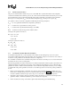
7.1.3 Local Ambient Temperature Measurement Guidelines
Local ambient temperature, T
LA
, is the temperature of the ambient air surrounding the processor. In a system
environment, ambient temperature is the temperature of the air upstream of the processor and in its close vicinity; or
in an active cooling solution; it is the inlet air to the active cooling device.
It is worthwhile to determine the local ambient temperature in the chassis around the processor to better understand
the effect it may have on the case temperature.
The following guidelines are meant to alleviate the non-uniform measurements found in typical systems. The local
ambient temperature is best measured as an average of the localized air surrounding the processor. The following
guidelines are meant to enable accurate determination of the localized air temperature around the processor during
system thermal testing. These guidelines are meant as a reasonable expectation to ensure the product specifications
are met.
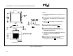
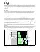
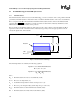
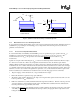
1. During system thermal testing, a minimum of two thermocouples should be placed approximately 0.5 to 1.0
inches (12.7 to 25.4mm) away from processor and heat sink as shown in the Figure 7. This placement guideline
is meant to minimize localized hot spots due to the processor, heat sink, or other system components.
2. The thermocouples should be placed approximately 2 inches (50.4mm) above the baseboard. This placement
guideline is meant to minimize localized hot spots from baseboard components.
3. The T
LA
should be the average of the thermocouple measurements during system thermal testing.