
Intel Pentium 4 Processor In the 423-pin Package Thermal Design Guidelines

Pentium® 4 processor in the 423-pin package Thermal Design Guidelines
20
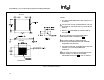
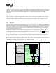
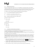
0.5 to 1.0”
Heatsink with Fan
Passive Heatsink
T
LA
Air Flow
T
LA
Air Flow
1.0”
~2”
000912a
Figure 7. Guideline Locations for Measuring Local Ambient Temperature
7.1.4 Measurements for Processor Thermal Specifications
To appropriately determine the thermal properties of the system, measurements must be made. Guidelines have been
established for proper techniques for measuring processor temperatures. The following sections describe these
guidelines for measurement.
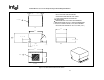
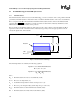
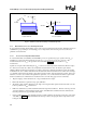
7.1.4.1 Processor Case Temperature Measurements
To ensure functionality and reliability, the Pentium® 4 processor is specified for proper operation when T
CASE
is
maintained at or below the value listed in the Pentium 4 processor in the 423-pin Package Datasheet. The
measurement location for T
CASE
is the geometric center of the IHS. Figure 8 shows the location for
T
CASE
measurement.
Special care is required when measuring the T
CASE
to ensure an accurate temperature measurement. Thermocouples
are often used to measure T
CASE
. Before any temperature measurements are made, the thermocouples must be
calibrated. When measuring the temperature of a surface, which is at a different temperature from the surrounding
local ambient air, errors could be introduced in the measurements. The measurement errors could be due to having a
poor thermal contact between the thermocouple junction and the surface of the integrated heat spreader, heat loss by
radiation, convection, by conduction through thermocouple leads, or by contact between the thermocouple cement
and the heat sink base. To minimize these measurement errors, the following approach is recommended:
• Prepare 36 gauge or finer diameter K, T, or J type insulated thermocouples.
• Ensure that the thermocouple has been properly calibrated.
• The thermocouple should be attached at a 90° angle to the integrated heat spreader and the heat sink covers the
location specified for T
case
measurement.
• Drill a hole 0.150 inches (3.8mm) maximum diameter through the heat sink base. This hole must be positioned
on the heat sink base so that it matches with the center of the IHS when assembled. This hole will reduce the
heat sink performance by approximately 0.02 °C/W.
• Create a small depression, approximately 1/16 inch (1.5mm) in diameter by 1/64 inch (.4mm) deep at the center
of the IHS (see Figure 8). This will facilitate the attach procedure by keeping the thermocouple centered and
hosting the adhesive.