
Intel Pentium 4 Processor In the 423-pin Package Thermal Design Guidelines

Pentium® 4 Processor in the 423-pin Package Thermal Design Guidelines
21
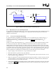
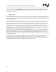
• Route the thermocouple wires through the hole in the heat sink base and attach it to the processor IHS. The use
of more viscous adhesives and minimizing the use of drying accelerators will prevent problems with the
adhesive spreading.
• A small fixture may be required to hold the thermocouple and apply a steady force during the curing process to
ensure the thermocouple is making contact with the IHS. A Digital Multi-Meter can be used to check continuity
between the IHS and the connector as the adhesive cures.
• Make sure there is no contact between the thermocouple adhesive and heat sink base. Contact will affect the
thermocouple reading.
• Verify the cured adhesive bead is smaller than 0.15 inches (3.8mm) in diameter and height so as to fit in the
hole drilled in the heat sink base. Trim as necessary.
• Place the TIM on the heat sink base. If it is a semi-liquid type apply it on the IHS around the thermocouple.
The clamping force will spread the TIM. If the TIM is a solid type, punch a 0.15inch (3.8mm) diameter hole in
the center of the TIM pad and cut a line from a side to the hole. This will allow the installation of the TIM to
the IHS with the thermocouple already attached to the IHS
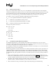
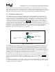
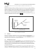
Measure from edge of processor
Measure T
at this point.
CASE
Thermal grease should cover the
entire surface of the Integrated
Heat Spreader
1.125”
1.075”
Figure 8. Processor IHS Temperature Measurement Location
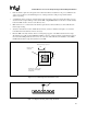
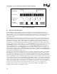
000900
Figure 9. Technique for Measuring with 90°
°°
° Angle Attachment