
Intel Pentium 4 Processor In the 423-pin Package Thermal Design Guidelines

Pentium® 4 Processor in the 423-pin Package Thermal Design Guidelines
27
models of the thermal diode sensors are described in datasheets available from the thermal diode sensor
manufacturers.
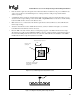
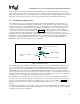
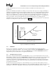
The processor thermal diode should not be relied upon to turn on fans, warn of processor cooling system failure or
predict the onset of thermal control circuit. As mentioned earlier, the processor’s high thermal ramp rates make this
unfeasible. An illustration of this is as follows. Many thermal diode sensors report temperatures a maximum of 8
times per second. Within the 1/8
th
(0.125 sec) second time period, the thermal diode temperature is averaged over
1/16
th
of a second. In a worst case scenario where the silicon temperature ramps at 30°C/sec, or ~3.75°C/0.125 sec,
the processor will be ~3°C above the temperature reported by the thermal diode sensor. (Change in diode
temperature averaged over 1/16
th
seconds = ~1°C, temperature reported 1/16
th
second later at 1/8
th
second when the
actual processor temperature would be 3.75°C higher, see Figure 14)
Figure 14. Thermal Diode Sensor Time Delay
8.5.2 THERMTRIP#
In the event of a catastrophic cooling failure, the processor will automatically shut down when the silicon
temperature has reached approximately ~135 °C. At this point the system bus signal THERMTRIP# will go active
and stay active until the processor has cooled down and RESET# has been initiated. THERMTRIP# activation is
independent of processor activity and does not generate any bus cycles.
8.5.3 Thermal Measurement Correlation
There are two independent thermal diodes in the Pentium® 4 processor; one for the thermal diode and one for the
Thermal Monitor, which is also used for THERMTRIP#. The Thermal Monitor’s temperature sensor and the thermal
diode are independent and isolated devices with no direct correlation to one another. Circuit constraints and
performance requirements prevent the Thermal Monitor sensor, and thermal diode from being located at the same
location on the silicon. As a result, it will not be possible to predict the activation of the thermal control circuit by
monitoring the thermal diode
If desired, the system may be designed to cool the maximum processor power levels. In this situation, it may be
useful to use the PROCHOT# signal as an indication of cooling system failure. Messages could be sent to the system
administrator to warn of the cooling failure, while thermal control circuit would allow the system to continue
Temperature
averaged over
1/16
th
second
Processor Temperature
Time in 1/16
th
seconds
Temperature
reported 1/16
th
second later
Processor thermal
ramp rate