
Intel Pentium 4 Processor In the 423-pin Package Thermal Design Guidelines


Pentium® 4 processor in the 423-pin package Thermal Design Guidelines
5
FIGURES
Figure 1. Pentium® 4 processor Package Outline........................................................................................................ 8
Figure 2. Example of Air Exchange through a PC Chassis........................................................................................ 10
Figure 3. Heat Sink Base Dimensions........................................................................................................................ 12
Figure 4. Heat Sink with Enabled Retention Mechanism .......................................................................................... 13
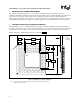
Figure 5. Fan Placement and Layout of an ATX Form Factor Chassis – Top View.................................................. 15
Figure 6. Thermal Resistance Relationships (Processor)........................................................................................... 18
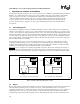
Figure 7. Guideline Locations for Measuring Local Ambient Temperature.............................................................. 20
Figure 8. Processor IHS Temperature Measurement Location .................................................................................. 21
Figure 9. Technique for Measuring with 90
°
Angle Attachment............................................................................... 21
Figure 10. Thermal Sense Circuit .............................................................................................................................. 23
Figure 11. Internal Clocks.......................................................................................................................................... 24
Figure 12. Application Power Dissipation Estimates for the Pentium 4 processor.................................................... 25
Figure 13. Processor Performance versus System Cooling Capability ...................................................................... 26
Figure 14. Thermal Diode Sensor Time Delay .......................................................................................................... 27