
Intel Pentium 4 Processor In the 423-pin Package Thermal Design Guidelines


Pentium® 4 processor in the 423-pin package Thermal Design Guidelines
9
4 THERMAL SPECIFICATIONS
Refer to the
Pentium 4 processor in the 423-pin Package Datasheet
, for the thermal specifications of the Pentium 4
processor.
In order to ease the burden on chassis cooling solutions a new Thermal Monitor feature has been integrated into the
silicon of the Pentium® 4 processor. By taking advantage of the Thermal Monitor feature, system designers may
reduce the cooling system cost while maintaining the processor reliability and performance goals. Other options
within the thermal management logic allow system software to monitor and control the thermal characteristics of the
processor. Implementation options and recommendations are described in Section 8.
4.1 Assumptions
For the purposes of this design guideline, the following reliability and operation assumptions have been made about
the processor:
•
Considering the power dissipation levels and typical system ambient environments of 35°C to 45°C, the
processor's temperature cannot be maintained at or below the specified guidelines without additional thermal
enhancement to dissipate the heat generated by the processor. In other words, a heat sink is required.
•
The thermal characterization data described in later sections illustrates that both a thermal-cooling device and
system airflow is needed. The size and type (passive or active) of thermal cooling device and the amount of
system airflow are related and can be traded off against each other to meet specific system design constraints. In
typical systems, board layout, spacing, and component placement limit the thermal solution size. Airflow is
determined by the size and number of fans, along with their placement in relation to the components and the
airflow channels within the system. In addition, acoustic noise constraints may limit the size, number, and types
of fans that can be used in a particular design.
To develop a reliable, cost-effective thermal solution, all of the above variables must be considered. Thermal
characterization and simulation should be carried out at the entire system level accounting for the thermal
requirements of each component.
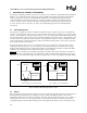
4.2 Processor Case Temperature
The Integrated Heat Spreader (IHS) is intended to provide the common interface and attach location for all thermal
solutions. The IHS acts to spread the concentrated heat from the core to a larger surface area, which will allow a
more efficient heat transfer to the heat sink. Thermal solutions can be active or passive. Active solutions incorporate
a fan in the heat sink and may be smaller than a passive heat sink. Passive thermal solutions do not incorporate a fan
in the heat sink. Considerations in heat sink design include:
•
Local ambient temperature at the heat sink
•
Surface area of the heat sink
•
Volume of airflow over the heat sink surface area
•
Power being dissipated by the processor
•
Physical volumetric constraints placed by the system
Techniques for measuring case temperatures are provided in Section 7.1.4.1.
4.3 Processor Power
The processor power, as listed in the Dataheet, is the total thermal design power that is dissipated through the IHS.