
Intel Pentium 4 Processor in the 423-pin Package Thermal Solution Functional Specification

®
Intel® Pentium® 4 Processor Thermal Solution Functional Specification
13
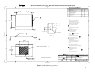
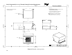
Intel’s thermal solution reference design uses direct chassis attach of the processor retention
mechanism.
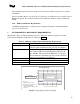
Intel recommends the use of 6-32 [x1/2-3/8”] pan head or round head screw [4 each] for direct
RM-chassis attach. The screw head must be less than 0.284” diameter and less than 0.190”
height.
4.10. EMI Ground Frame Requirements
An EMI grounding frame to reduce the electro-magnetic interference from the Pentium 4
processor is unnecessary.
5. ENVIRONMENTAL RELIABILITY REQUIREMENTS
The thermal solution assembly (including all of its components) shall be designed to meet the
environmental reliability requirements as outlined in Table 2.
Table 2: Summary of Environmental Reliability Requirements
Test Level
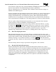
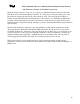
Mechanical Shock
30 G, ∆V=170 in/s, ~11 ms trapezoidal waveform
3 drops in each of 6 directions (±X, ±Y, ±Z). See Figure 5.
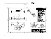
Vibration Random vibration input of 0.001 g
2
/Hz at 5 Hz, sloping to
0.01 g
2
/Hz at 20 Hz, and maintaining 0.01 g
2
/Hz from 20
Hz to 500 Hz. The area under the PSD curve is 2.20 g
RMS
.
The test duration is 10 minutes per axis in each of the three
primary axes sequentially. See Figure 6.
Temperature Cycling -25C to 100C, 10-30C/min ramp, 15min dwell, 192 cycles
Temperature Humidity 95C, 85%RH, 14 days
Bake Test 95C, 16days, nominal (<25%) RH
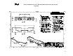
Shock (Unpackaged)
0
5
10
15
20
25
30
35
0 5 10 15
Time (ms) -( for reference only)
Shock input
acceleration (g’s)
"
Qty: 3 units
"
3 drops per each of 6 faces
"
∆
V = 170 in/s = area under curve
"
Table profile is idealized
(0 to 30 G ramp should be as fast as
practical)
∆
V = 170 in/s
Figure 5. Unpackaged system shock input