
Intel Pentium 4 Processor in the 423-pin Package Thermal Solution Functional Specification

®
Intel
®
Pentium® 4 Processor Thermal Solution Functional Specification
7
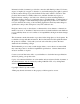
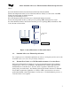
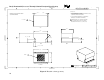
Where,
θsa is the thermal resistance measured between the heat sink and ambient
Tsink is the temperature at the bottom of the heat sink base directly over the center of the IHS
Tamb is the temperature at ambient location
Q is the power from the processor
θcs is the thermal resistance measured across the thermal interface material
Tcase is the temperature at the top of the processor package (IHS) measured at its center
θca is the thermal resistance measured between the processor package (IHS) and ambient. This
is also the sum of θcs and θsa.
θ
θθ
θ
sink-ambient
[
θ
θθ
θ
sa
]
θ
θθ
θ
case-sink
[
θ
θθ
θ
cs]
T amb
Tcase*
Q(power)*
θ
θθ
θ
case-ambient
[Rca]
θ
θθ
θ
ca =
θ
θθ
θ
cs +
θ
θθ
θ
sa
Processor Package
(
IHS
)
H
eat Sink
Interface Mat'l
* From Datasheet
Figure 2: Overall Resistance for Thermal Solution
3.1.
Pentium® 4 Processor Thermal Specifications
For complete processor thermal requirements at various core frequency levels, refer to the
Pentium® 4 processor in the 423-pin Package Datasheet.
3.2.
Thermal Test Vehicle –to- CPU Thermal Performance Correction Factor
Intel releases Thermal Test Vehicles for use by system and heat sink solution thermal
designers prior to Processor availability. The Thermal Test Vehicles approximate the
thermal behavior of the Processor; however, there is typically a difference in power
density and power uniformity. Any thermal solution performance measured on Thermal
Test Vehicles requires the application of a TTV-to-CPU correction factors in order to
predict that thermal solution performance on a Processor. For the Pentium 4 processor, a
correction factor is not required.