
Intel Pentium 4 Processor in the 478-pin Package / Intel 850 Chipset Platform Family Design Guide
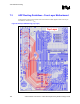

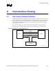

Hub Interface Routing
R
130 Intel
®
Pentium
®
4 Processor / Intel
®
850 Chipset Family Platform Design Guide
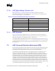
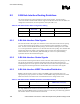
8.2.4 8-Bit Hub Interface Compensation
The hub interface uses a compensation signal to adjust buffer characteristics to the specific board
characteristic. The hub interface requires Resistive Compensation (RCOMP).
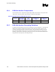
Table 32. 8-Bit Hub Interface RCOMP Resistor Values
Component Hub Interface
Buffer Mode
Trace
Impedance
RCOMP Resistor
Value
RCOMP Resistor
Tied to
ICH2 Normal 60 Ω ± 15% 40 Ω ± 2% or 39 Ω ± 1% VCC1_8
MCH Normal 60 Ω ± 15% 40 Ω ± 2% or 39 Ω ± 1% VSS
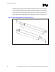
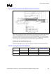
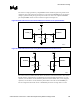
8.2.5 8-Bit Hub Interface Decoupling Guidelines
To improve I/O power delivery, use two 0.1 µF capacitors per each component (i.e., the ICH2 and
MCH). These capacitors should be placed within 150 mils from each package, adjacent to the
rows that contain the hub interface. If the layout allows, wide metal fingers running on the VSS
side of the board should connect the VCC1_8 side of the capacitors to the VCC1_8 power pins.
Similarly, if layout allows, metal fingers running on the VCC1_8 side of the board should connect
the ground side of the capacitors to the VSS power pins.