
Intel Pentium 4 Processor in the 478-pin Package / Intel 850 Chipset Platform Family Design Guide

I/O Controller Hub 2
R
138 Intel
®
Pentium
®
4 Processor / Intel
®
850 Chipset Family Platform Design Guide
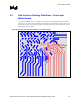
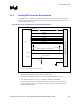
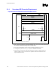
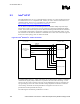
9.1.4 Secondary IDE Connector Requirements
Figure 90. Connection Requirements for Secondary IDE Connector
SDD[15:0]
SDA[2:0]
SDCS1#,SDCS3#
SDIOR#
SDIOW#
SDDREQ
SDDACK#
IDE_secondary_conn_require
PDIAG# / CBLID#
CSEL
* Due to ringing, PCIRST# must be buffered.
3.3 V
3.3 V
4.7 kΩ
8.2–10 kΩ
10 kΩ
PCIRST#*
SIORDY
IRQ15
GPIOy
ICH2
Secondary IDE Connector
22–47 Ω
• 22 Ω – 47 Ω series resistors are required on RESET#. The correct value should be determined
for each unique motherboard design, based on signal quality.
• An 8.2 kΩ to 10 kΩ pull-up resistor is required on IRQ14 and IRQ15 to VCC3_3.
• A 4.7 kΩ pull-up resistor to VCC3_3 is required on PIORDY and SIORDY
• Series resistors can be placed on the control and data line to improve signal quality. The
resistors are place as close to the connector as possible. Values are determined for each
unique motherboard design.