
Intel Pentium 4 Processor in the 478-pin Package / Intel 850 Chipset Platform Family Design Guide

I/O Controller Hub 2
R
180 Intel
®
Pentium
®
4 Processor / Intel
®
850 Chipset Family Platform Design Guide
9.9.5 Intel
®
82562 ET/EM Disable Guidelines
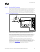
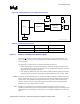
To disable the 82562ET/EM, the device must be isolated (disabled) prior to reset
(RSM_PWROK) asserting. Using a GPIO, such as GPO28 to be LAN_Enable (enabled high),
LAN will default to enabled on initial power-up and after an AC power loss. This circuit
(see Figure 128) will allow this behavior. BIOS by controlling the GPIO can disable the LAN
microcontroller.
Figure 128. Intel
®
82562ET/EM Disable Circuit
Intel
®
82562ET/EM_Disable
Out
In
10 kΩ
In
Out
10 kΩ
RSM_PWROK
GPIO_LAN_ ENABLE
V
CC
SUS3_3
Q4301L
MMBT3906
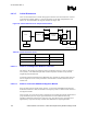
There are 4 pins which are used to put the 82562ET/EM controller in different operating states:
Test_En, Isol_Tck, Isol_Ti, and Isol_Tex. The table below describes the operational/disable
features for this design.
Test_En Isol_Tck Isol_Ti Isol_Tex State
0 0 0 0 Enabled
0 1 1 1 Disabled w/ Clock (low power)
1 1 1 1 Disabled w/out Clock (lowest power)
The four control signals shown in the above table should be configured as follows: Test_En should
be pulled-down thru a 100 Ω resistor. The remaining 3 control signals should each be connected
thru 100 Ω series resistors to the common node “82562ET/EM_Disable” of the disable circuit.