
Intel Pentium 4 Processor in the 478-pin Package / Intel 850 Chipset Platform Family Design Guide

Intel® Pentium® 4 Processor in the 478-Pin Package Processor Power Distribution Guidelines
R
222 Intel
®
Pentium
®
4 Processor / Intel
®
850 Chipset Family Platform Design Guide
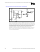
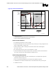
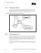
Figure 165. Example Circuit That Can Be Used As a Thermal Monitor
0.1uF
3904
LM393
Vcc
6.8k
THMSTR
7.5kΩ
+
-
1kΩ
R2
499Ω
130Ω
R1
1kΩ
680Ω
130Ω
Vcc
Vccp
PROCHOT#
3.
For this circuit implementation, the thermistor (THMSTR) should be placed in the hottest area of
the VR. As the thermistor heats up its resistance goes down. This creates an error voltage based on
the resistance of the thermistor and the voltage reference provided by R1 and R2. The values of R1
and R2 should be adjusted to calibrate the circuit for a specific system board design so that it
asserts PROCHOT# when the VR reaches its thermal limit. The values for R1 and R2 in Figure 1
are included as an example. The value of R2 is adjusted to calibrate the circuit so that
PROCHOT# is asserted when the VR reaches its thermal limit in the system that it is intended to
operate. An adequate VR cooling solution should be implemented such that VR_TDT current
levels can be maintained indefinitely.