
Intel Pentium 4 Processor in the 478-pin Package / Intel 850 Chipset Platform Family Design Guide

Intel® Pentium® 4 Processor in the 478-Pin Package Processor Power Distribution Guidelines
R
Intel
®
Pentium
®
4 Processor / Intel
®
850 Chipset Family Platform Design Guide 223
11.3 Simulation
11.3.1 FMB1
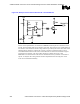
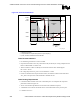
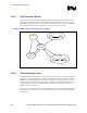
To completely model the system board, one must include the inductance and resistance that exists
in the cables, connectors, PCB planes, pins and body of components (such as resistors and
capacitors), processor socket, and the voltage regulator module. More detailed models showing
these effects are shown in Figure 166.
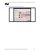
Figure 166. Detailed Power Distribution Model for Processor with Voltage Regulator on
System Board
OSCONs south
1206s on north
1206s on south
1206s in cavity
(north)
1206s in cavity
(south)
OSCONs north
Processor Equivalent Model
L1 L2 L3 L4 L5 L6 L7
R=25mΩ
ΩΩ
Ω/42
L=3.3nH/42
R=25mΩ
ΩΩ
Ω/41
L=3.3nH/41
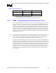
Table 53 lists model parameters for the system board shown in Figure 166.
Table 53. Intel
®
Pentium
®
4 Processor Power Delivery Model Parameters
Segment Resistance Inductance
L1 0.24 mΩ 29 pH
L2 0.23 mΩ 37 pH
L3 0.293 mΩ 68 pH
L4 0.144 mΩ 27 pH
L5 0.293 mΩ 68 pH
L6 0.14 mΩ 35 pH
L7 0.14 mΩ 28 pH