
Intel Pentium 4 Processor in the 478-pin Package / Intel 850 Chipset Platform Family Design Guide

Power Distribution Guidelines
R
Intel
®
Pentium
®
4 Processor / Intel
®
850 Chipset Family Platform Design Guide 231
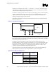
Table 55. Intel
®
850 Chipset and Intel
®
ICH2 Thermal Design Power
Parameter Icc Max Sustainable
Current (A) S0)
MCH
• MCH (UP) Typical Thermal Design Power = 5.8 W
• MCH (UP) Maximum Thermal Design Power = 8.0 W
1.8 V Core 3.2
1.5 V VDDQ AGP I/O 0.37
1.6 V VTT 2.2
ICH2
• Max Thermal Design Power = 1.6 W ±15%
1.8 V Main Logic 0.30
1.8 V (Stand By) Resume Logic + 1.8 V LAN 0.040
3.3 V Main I/O 0.41
3.3 V (Stand By) Resume Logic 0.062
RTC .04 (G3)
Processor I/F (1.3 ~ 2.5) 200 uA
NOTE: Remember that values stated for the maximum sustainable current (Icc) of the ICH2 are maximum
preliminary measurements, and are subject to change.
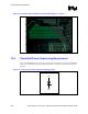
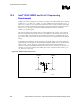
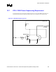
12.3 1.8 V RAC Isolation Solution
The MCH requires a low-pass filter on the VccRAC pins to meet clock jitter specifications. The
two possible filter solutions may be configured as either an inductor-capacitor (LC) or ferrite
bead-capacitor filters. For more details, see Figure 172 and Figure 173. The inductor or ferrite
bead must have a minimum current capacity of 500 mA and a maximum DC resistance of 100 mΩ.
DC drop is a concern due to the series element between the RAC and 1.8 V supply. The VccRAC
pins for the MCH are given in Table 56.
Figure 172. Inductor-Capacitor Filter Circuit
1.8 V
L
C1
C2
Vcc
Core
VccRAC
MCH
Ind_Cap_Filter