
Intel Pentium 4 Processor in the 478-pin Package / Intel 850 Chipset Platform Family Design Guide

Schematic Review Checklist
R
248 Intel
®
Pentium
®
4 Processor / Intel
®
850 Chipset Family Platform Design Guide
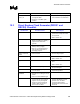
15.2 CK00 Clock Generator Checklist
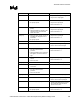
Checklist Items Recommendations Reason/Impact/Documentation
Ref/MultSel[0:1] • Use 33 Ω series termination resistor
for each signal.
• Connect to ICH2 and SIO.
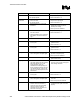
PCICLK [0:9] • Use 33 Ω series termination resistor
for each signal.
• Connect to PCI slots 0 through 4
• Connect to ICH2, FWH, SIO, Glue
Chip and Audio Logic Device.
• Refer to Section 4.4.2.1.
3V66 [0:3] • Use 33 Ω series termination resistor
for each signal.
• Connect to AGP Connector, MCH,
and ICH2.
• Refer to Section 4.4.2.
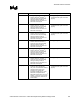
3VMRef
3VMRef_b
• Use 33 Ω series termination resistor
for each signal.
• Connect 3VMRef to DRCG1.
• Connect 3VMRef_b to DRCG2
• 3VMRef_b is 180
o
out of phase with
3VMRef.
SEL100/133 • Connect this signal to GND with a
470
Ω ±5% resistor.
• Connect this signal to processor pin
BSEL0 with a 1 k
Ω ±5% resistor
pull-up to VCC3_CLK
• This signal needs to be connected to
GND for 100 MHz host clock
operation only
• This connection option allows 100
MHz or 133 MHz host clock
operation.
48 MHz /SelA
48 MHz /SelB
• Terminate to GND with 1 kΩ ±5%
resistors
• Terminating to GND sets CK00 for
100 MHz or 133 MHz host clock
operation
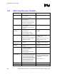
SPREAD# • Terminate to GND with a 470 Ω ±5%
resistor.
• Terminating to GND enables this
function
PWRDWN# • Used to prevent platform from
booting with unsupported
processors. See Section 4.2 for
more information.
• Connect to DRCG1 and DRCG2
clock generators.
CPUCLK/
CPUCLK_B[0:3]
• Connect a 33 Ω ±5% series resistor
on each clock signal. Series resistor
should be placed on the clock driver
side of the shunt source resistor.
• Connect a “shunt source termination
(Rt)” resistor to GND for each signal
after series termination resistor.
• Connect differential clock pair to
processor, MCH, ITP connector.
• These are differential clocks.
• Rt resistors should be selected to
match the characteristic impedance
of the board.
• Refer to Section 4.1
3.3 V(VCC) • Connect to 3.3 V power plane
GND • Connect to GND plane.