
Intel Pentium 4 Processor in the 478-pin Package / Intel 850 Chipset Platform Family Design Guide

Schematic Review Checklist
R
Intel
®
Pentium
®
4 Processor / Intel
®
850 Chipset Family Platform Design Guide 257
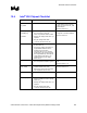
Checklist Items Recommendations Reason/Impact
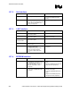
VCMOS
decoupling
• PC1066: Minimum of 2 x 0.1 µF
capacitors, one near each RIMM
input
• PC1066 requirement
2.5 V (VDD)
decoupling
• Low frequency decoupling:
• This needs to be done on the
motherboard with bulk capacitors.
• Linear regulator design: 8x 100 µF
• Switching regulator: 5x 47µF or
6x 20
µF
• PC1066: minimum of 2 x 1000 µF, 2
x 510 µF and 8 x 10 µF MLC
capacitors.
• These are EXAMPLES. The exact
decoupling requirements are
dependent on the voltage regulator
design. Refer to the RDRAM device
specification for the power delivery
requirements.
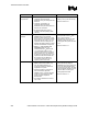
1.8 V (V
TERM
)
decoupling
• PC600/PC800 High frequency
decoupling:
One 0.1 µF ceramic capacitor per 2
RSL signals. These should be
placed near the termination
resistor pack.
• PC600/PC800 Low frequency
decoupling:
2 x 100 µF tantalum capacitors.
• PC1066 High frequency decoupling:
One 0.1 µF ceramic capacitor per 2
RSL signals (minimum of 13 x 0.1
µF capacitors). These should be
placed near the termination
resistor pack. For margin
improvement, this can be
increased to two 0.1 µF capacitors
per 2 RSL signals.
2 x 10 µF MLC
• PC1066 Low frequency decoupling:
2 x 100 µF tantalum capacitors
• RSL termination voltage decoupling is
required on the motherboard. Both
high and low frequency decoupling
needs to be added on the
motherboard.
• These are EXAMPLES. The exact
decoupling requirements are
dependent on the voltage regulator
design. Refer to the RDRAM device
specification for the power delivery
requirements.
• Refer to Section 6.1.3.