
Intel Pentium 4 Processor in the 478-pin Package / Intel 850 Chipset Platform Family Design Guide

Schematic Review Checklist
R
260 Intel
®
Pentium
®
4 Processor / Intel
®
850 Chipset Family Platform Design Guide
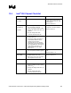
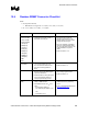
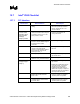
15.7.2 Hub Interface
Checklist Items Recommendations Reason/Impact
HL[11] • No pull-up resistor required • Use a no-stuff or a test point to put
the ICH2 into NAND chain mode
testing
HL_COMP • Tie the COMP pin to a 40 Ω 1% or
2% (or 39
Ω 1%) pull-up resistor (to
VCC1_8) via a 10-mil wide, very
short (~0.5 inch) trace.
• ZCOMP No longer supported.
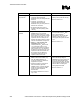
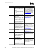
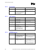
15.7.3 LAN* Interface
Checklist Items Recommendations Reason/Impact
LAN_CLK • Connect to LAN_CLK on platform
LAN connect device.
LAN_RXD[2:0] • Connect to LAN_RXD on platform
LAN connect device.
• ICH2 contains integrated 9 kΩ pull-up
resistors on interface
LAN_TXD[2:0]
LAN_RSTSYNC
• Connect to LAN_TXD on platform
LAN connect device.
•
• LAN connect interface can be left
NC if not used.
• Input buffers internally terminated
• In the event of EMI problems during
emissions testing (FCC
Classifications) you may need to
place a decoupling capacitor
(~470 pF) on each of the 4 LED
pins.
• Reduces emissions attributed to LAN
subsystem.
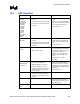
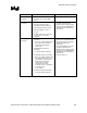
15.7.4 EEPROM Interface
Checklist Items Recommendations Reason/Impact
EE_DOUT • Prototype Boards should include a
placeholder for a pull-down resistor
on this signal line, but do not
populate the resistor. Connect to
EE_DIN of EEPROM or CNR
Connector.
• Connected to EEPROM data input
signal
• (Input from EEPROM perspective and
output from ICH2 perspective)
EE_DIN • No extra circuitry required. Connect
to EE_DOUT of EEPROM or CNR
Connector.
• ICH2 contains integrated pull-up
resistor for this signal.
• Connected to EEPROM data output
signal
• (Output from EEPROM perspective
and input from ICH2 perspective)