
Intel Pentium 4 Processor in the 478-pin Package / Intel 850 Chipset Platform Family Design Guide

Schematic Review Checklist
R
Intel
®
Pentium
®
4 Processor / Intel
®
850 Chipset Family Platform Design Guide 261
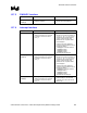
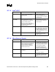
15.7.5 FWH/LPC Interface
Checklist Items Recommendations Reason/Impact
FWH[3:0]/ LAD[3:0]
LDRQ[1:0]
• No extra pull-ups required. Connect
straight to FWH/LPC.
• ICH2 integrates 24 kΩ pull-up
resistors on these signal lines.
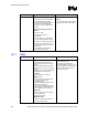
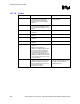
15.7.6 Interrupt Interface
Checklist Items Recommendations Reason/Impact
PIRQ#[D:A] • These signals require a pull-up
resistor. Recommend a 2.7 k
Ω pull-
up resistor to VCC5 or 8.2 k
Ω to
VCC3_3.
• In Non-APIC Mode the PIRQx#
signals can be routed to interrupts 3,
4, 5, 6, 7, 9, 10, 11, 12, 14 or 15 as
described in the Interrupt Steering
section of this document. Each
PIRQx# line has a separate Route
Control Register.
• In APIC mode, these signals are
connected to the internal I/O APIC in
the following fashion:
- PIRQ[A]# is connected to IRQ16,
- PIRQ[B]# to IRQ17,
- PIRQ[C]# to IRQ18,
- PIRQ[D]# to IRQ19.
This frees the ISA interrupts.
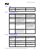
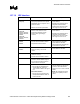
PIRQ#[G:F]/
GPIO[4:3]
• These signals require a pull-up
resistor. Recommend a 2.7 k
Ω pull-
up resistor to VCC5 or 8.2 k
Ω to
VCC3_3.
• In Non-APIC Mode the PIRQx#
signals can be routed to interrupts 3,
4, 5, 6, 7, 9, 10, 11, 12, 14 or 15 as
described in the Interrupt Steering
section of this document. Each
PIRQx# line has a separate Route
Control Register.
• In APIC mode, these signals are
connected to the internal I/O APIC in
the following fashion:
- PIRQ[E]# is connected to IRQ20,
- PIRQ[F]# to IRQ21,
- PIRQ[G]# to IRQ22,
- PIRQ[H]# to IRQ23.
This frees the ISA interrupts.
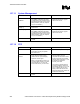
PIRQ#[H]
PIRQ#[E]
• These signals require a pull-up
resistor. Recommend a 2.7 k
Ω pull-
up resistor to VCC5 or 8.2 k
Ω to
VCC3_3.
• Since PIRQ[H]# and PIRQ[E]# are
used internally for LAN and USB
controllers, they cannot be used as
GPIO(s) pin.