
Intel Pentium 4 Processor in the 478-pin Package / Intel 850 Chipset Platform Family Design Guide

Schematic Review Checklist
R
Intel
®
Pentium
®
4 Processor / Intel
®
850 Chipset Family Platform Design Guide 267
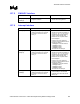
15.7.16 IDE Interface
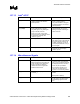
Checklist Items Recommendations Reason/Impact
PDD[15:0],
SDD[15:0]
• No extra series termination resistors or
other pull-ups/pull-downs are required.
• PDD7/SDD7 does not require a 10 kΩ
pull-down resistor.
• Refer to ATA ATAPI-4 specification.
• These signals have integrated
series resistors.
• Simulation data indicates that the
integrated series termination
resistors are a nominal 33
Ω but
can range from 31
Ω to 43 Ω.
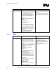
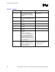
PDIOW#, PDIOR#,
PDDACK#,
PDA[2:0], PDCS1#,
PDCS3#, SDIOW#,
SDIOR#,
SDDACK#,
SDA[2:0], SDCS1#,
SDCS3#
• No extra series termination resistors.
Pads for series resistors can be
implemented should the system
designer have signal integrity
concerns.
• These signals have integrated
series resistors.
• Simulation data indicates that the
integrated series termination
resistors are a nominal 33
Ω but
can range from 31
Ω to 43 Ω.
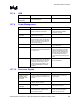
PDREQ
SDREQ
• No extra series termination resistors.
• No pull-down resistors needed.
• These signals have integrated
series resistors in the ICH2.
• These signals have integrated pull-
down resistors in the ICH2.
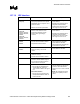
PIORDY
SIORDY
• No extra series termination resistors.
• Pull-up to VCC3_3 via a 4.7 kΩ
resistor.
• These signals have integrated
series resistors in the ICH2.
IRQ14, IRQ15 • Recommend 8.2 kΩ–10 kΩ pull-up
resistors to VCC3_3.
• No extra series termination resistors.
• Open drain outputs from drive.
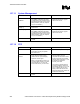
IDERST# • The PCIRST# signal should be
buffered to form the IDERST# signal.
A 33
Ω series termination resistor is
recommended on this signal.
Cable Detect: • Host Side/Device Side Detection
Connect IDE pin PDIAG/CBLID to
an ICH2 GPIO pin. Connect a
10 k
Ω resistor to GND on the signal
line.
• Device Side Detection
Connect a 0.047 µF capacitor from
IDE pin PDIAG/CBLID to GND. No
ICH2 connection.
• The 10 kΩ resistor to GND prevents
GPI from floating if no devices are
present on either IDE interface.
Allows use of 3.3 V and 5 V tolerant
GPIOs.
• NOTE: All ATA66/ATA100 drives
will have the capability to detect
cables