
Intel Pentium 4 Processor in the 478-pin Package / Intel 850 Chipset Platform Family Design Guide

Layout Review Checklist
R
Intel
®
Pentium
®
4 Processor / Intel
®
850 Chipset Family Platform Design Guide 271
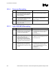
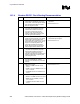
16.1.2 Asynchronous GTL+ and Other Signals
√ Recommendations Reason/Impact/Documentation
• FERR# and PROCHOT connects with the
“T” topology. Processor to
T-junction should be 1 inch–12 inches.
Connection to the ICH2 should be made
with no stub. T- junction to pull-up should be
3 inches max. A 7 mil spacing is required.
Trace impedance should be 60
Ω.
• Refer to Section 5.4.1
• A20M#, IGNNE#, INIT#, LINT[1:0],
SLP#,SMI# and STPCLK# connect in a
point-to-point topology. Trace length should
be 12 inches max. A 7 mil spacing required.
Trace impedance should be 60
Ω.
• Refer to Section 5.4.1
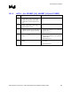
• THERMTRIP# connects in a “T” topology.
Processor to T-junction should be 1 inch–
12 inches max. Connection to the ICH2
should be made with no stub. T junction to
pull-up resistor should be 3 inches max.
Trace impedance should be 60
Ω. Trace
spacing should be 7 mils.
• Refer to Section 5.4.1
• PWRGOOD connected in a “T” topology.
Pull-up resistor to T-junction should be
3 inches max. T-junction to processor
should be 1.1 inches max.
T-junction to ICH2 should be 1–12 inches
Trace impedance should be 60
Ω. Trace
spacing should be 7 mils.
• Refer to Section 5.4.1
• THERMDA/THERMDC should connect to
remote sensor within 4-8 inches as long as
worst-case noise sources (e.g., the clock
generator, data and address signals) are
avoided. A 10 mil wide trace recommended.
Shielded twisted pair recommended for long
distance remote sensor.
• Refer to Section 5.4.1
• VCCIOPLL, VCCA, VSSA circuitry should
be routed away from noisy signals or high
free signals. Keep traces as short as
possible.
• Refer to Section 5.5.
• Place 51.1 Ω ±1% resistors as close to
COMP[1:0] as possible
• Refer to Section 5.4.1
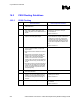
16.1.3 Processor Keep-Out Zones
√ Recommendations Reason/Impact/Documentation
• Refer to Chapter 10.