
Intel Pentium 4 Processor in the 478-pin Package / Intel 850 Chipset Platform Family Design Guide

Layout Review Checklist
R
272 Intel
®
Pentium
®
4 Processor / Intel
®
850 Chipset Family Platform Design Guide
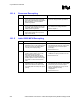
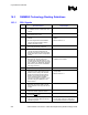
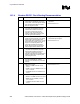
16.1.4 Processor Decoupling
√ Recommendations Reason/Impact/Documentation
• Place ten 560 µF OS-CON capacitors as
close to the processor power and ground
pins as the heatsink keepout area will allow.
Refer to Chapter 11 for more detailed
placement guidelines.
• These capacitors are needed to meet the
processor voltage transient specifications.
• Place 30 1206 package 10 µF capacitors as
close to processor ground and power pins
as possible. Refer to Chapter 11 for more
detailed placement guidelines.
• These high frequency decoupling capacitors
are needed to meet voltage transients.
• Refer to Chapter 11.
• All capacitors should be placed as close to
the processor package as the processor
keep-out zone allows.
• Refer to Chapter 11.
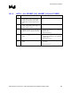
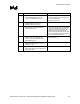
16.1.5 Intel
®
82850 MCH Decoupling
√ Recommendations Reason/Impact/Documentation
• 4–5 0.1 µF capacitors with 603 packages
distributed evenly over the system bus data
lines. Place as close as possible (within
150 mils) to the chipset package.
• This recommendation reduces return path
discontinuities that result from system board
traces having only one reference plane
(microstrip).
• Refer to Section 5.5.1
• V
CC
RAC isolation: Low pass filter circuit
should be located within 2 inches of the
MCH and the layout of V
CC
RAC
connections should follow high-speed
design practices. Decoupling capacitors
should be placed as close to the RAC pins
as possible to control self-induced RAC
noise.
• Proper routing of V
CC
RAC isolation ensures
RAMBUS clock jitter specifications are met.
• Refer to Section 12.3.
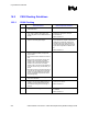
• 2–3 0.1 µF capacitors with 603 packages
distributed evenly over the system bus
address and control lines. Place as close
as possible (within 150 mils) to the chipset
package.
• This recommendation reduces return path
discontinuities that result from system board
traces having only one reference plane.
These recommendations are only used for
designs containing microstrip
configurations.
• Refer to Section 5.5.1