
Intel Pentium 4 Processor in the 478-pin Package / Intel 850 Chipset Platform Family Design Guide

Layout Review Checklist
R
278 Intel
®
Pentium
®
4 Processor / Intel
®
850 Chipset Family Platform Design Guide
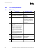
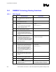
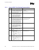
16.3.2 Ground Isolation
√ Recommendations Reason/Impact
• Via to ground every ½ inches around edge
of isolation island, between RIMM
connectors and between RSL signals (from
MCH to 1
St
RIMM connector)
In channel Ideal: 5 inches
Acceptable: 0 inches
At end Ideal: 25 inches
Acceptable: 5 inches
* If 3/4 inch end of ground plane: shorten
ground plane by 1/4 inch to meet ½ inch
recommendation.
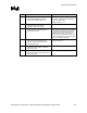
• Via between every signal within 100 mils of
the MCH edge and the RIMM connector
edge.
• No unconnected ground floods • To avoid discontinuity in ground planes.
• Ground isolation fills between serpentines • To avoid cross talk.
• Ground isolation not broken by C-tabs • To avoid discontinuity in the ground plane.
• Refer to Section 6.1.2.5.
• Ground isolation connects to the ground
pins in the middle of the RIMM connector.
• Ground isolation vias connect on all layers
and should NOT have thermal relieves.
• Ground pins in RIMM connector should
connect on all layers.