
Intel Pentium 4 Processor in the 478-pin Package / Intel 850 Chipset Platform Family Design Guide


Layout Review Checklist
R
Intel
®
Pentium
®
4 Processor / Intel
®
850 Chipset Family Platform Design Guide 285
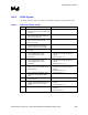
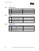
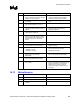
16.4.4 AGP Connector Decoupling
√ Recommendations Reason/Impact
• One 0.01 µF capacitor next to each power
pin on connector, VCC1_5, V
DDQ
, +5, +12,
3.3VAUX.
• Refer to Section 7.1.11.
• For Bulk decoupling, need one 10 µF
tantalum capacitor to V
DDQ
and a 20 µF
tantalum capacitor on VCC3_3 plane near
connector.
• Refer to Section 7.1.11.
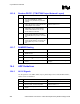
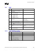
16.5 8 Bit Hub Interface
√ Recommendations Reason/Impact
• Board impedance needs to be
60
Ω ±15%
• Refer to Section 8.2.
• Traces need to be routed 5 mils wide with
20 mils spacing
• Refer to Section 8.2.
• To breakout of the MCH and ICH2 package
the hub interface signals can be routed 5 on
5. Signals need to be separated to 5 on 20
within 300 mils of the package.
• Refer to Section 8.2.
• Max trace length is 6 inches long. • Refer to Section 8.2.
• Data signals must be matched within
±0.1 inches of the HL_STB diff pair.
• Refer to Section 8.2.2.
• Each strobe signal needs to be the same
length.
• Refer to Section 8.2.2.
• HUBREF divider should be placed no more
than 3.5 inches of away from MCH or ICH2.
If so then need separate resistor divider
placed locally.
• Refer to Section 8.2.3.
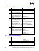
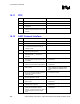
16.5.1 Hub Decoupling
√ Recommendations Reason/Impact
• Two 0.1 µF capacitors per each component
(MCH and ICH2) spread over the Hub
Interface.
• Refer to Section 8.2.5.
• Place within 150 mils of each package. • Refer to Section 8.2.5.