
Intel Pentium 4 Processor in the 478-pin Package / Intel 850 Chipset Platform Family Design Guide


Layout Review Checklist
R
Intel
®
Pentium
®
4 Processor / Intel
®
850 Chipset Family Platform Design Guide 287
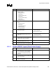
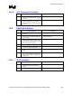
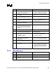
16.9 USB
√ Recommendations Reason/Impact
• Characteristic impedance of individual
signal lines P+, P- Zo = 45
Ω (90 Ω
Differential)
• Refer to Section 9.4.
• Stack-up: 9 mils wide, 25 mil spacing
between Differential pairs
• Refer to Section 9.4.
• Trace Characteristics:
Line Delay = 160.2 ps
Capacitance = 3.5 pF
Inductance = 7.3 nH
Res @ 20o C = 53.9 mΩ
• Refer to Section 9.4.
• 15 Ω series resistor to be placed < 1 inch
from ICH2
• This is required for source termination of the
reflected signal.
• Refer to Section 9.4.
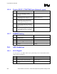
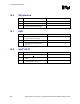
• 47 pF parallel capacitors should be placed
as close to the ICH2 as possible
• Refer to Section 9.4.
• 15 kΩ + 5% pull-down resistors should be
placed as close to the ICH2 as possible.
• Refer to Section 9.4.
• Optional 47 pF capacitor placed close to the
USB connector as possible to the USB data
lines
• This capacitor can be used for signal quality
(rise/fall) times and to help minimize EMI
radiation
• Refer to Section 9.4 of this document.
• Stub length due to 15 kΩ pull-downs should
be as short as possible.
• Refer to Section 9.4.
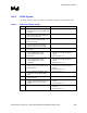
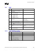
16.10 Intel
®
ICH2 Decoupling
√ Recommendations Reason/Impact
• 3.3 V Core—six 0.1 µF capacitors • Refer to Section 9.12.
• 3.3 V Stand By –one 0.1 µF capacitor • Refer to Section 9.12.
• Processor I/F (Vcc
_Core
) –one 0.1µF
capacitor
• Refer to Section 9.12.
• 1.8 V Core–two 0.1 µF capacitors, already
included in Hub decoupling
• Refer to Section 9.12.
• Place Decoupling capacitors as close to the
ICH2 as possible (~ 400 mils)
• Refer to Section 9.12.