
Intel Pentium 4 Processor in the 478-pin Package / Intel 850 Chipset Platform Family Design Guide


Platform Placement and Stack-Up Overview
R
Intel
®
Pentium
®
4 Processor / Intel
®
850 Chipset Family Platform Design Guide 31
3 Platform Placement and Stack-Up
Overview
In this section, examples of Intel 850 chipset platform component placement and stack-up are
described for desktop systems in 6-layer ATX and 4-layer µATX motherboard form factors.
3.1 Platform Component Placement
3.1.1 Six-Layer Motherboard
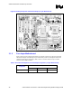
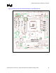
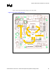
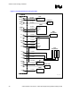
Figure 5 shows general component placement for a Pentium 4 processor in the 478-pin package
and Intel 850 chipset-based desktop 6-layer motherboard system. The assumptions used for the
component placement are described in Table 3 and are consistent with the 6-layer customer
reference board (CRB) schematics.
Note: The processor supports uni-processor configurations only.
Table 3. Placement Assumptions for the Desktop Configuration (6-Layer Motherboard)
Assumptions
System
Configuration
Form Factor Number of
Layers for
Routing
Assembly
Uni-processor ATX 6 layers Single sided