
Intel Pentium 4 Processor in the 478-pin Package / Intel 850 Chipset Platform Family Design Guide
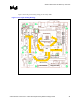

Platform Placement and Stack-Up Overview
R
36 Intel
®
Pentium
®
4 Processor / Intel
®
850 Chipset Family Platform Design Guide
3.2 Motherboard Layer Stack-Up
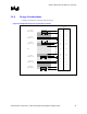
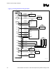
3.2.1 Six-Layer Motherboard Stack-Up
Figure 8 shows a six-layer stack-up for the system. It is for reference only and the actual board
stack-up may vary depending upon the following considerations. The separation between layers 2
and 3 should be kept as large as possible. A distance greater than 2x should be kept between
signals on layers 2 and signals on layer 3. Additionally, traces on layer 2 should be routed
orthogonally to traces on layer 3. If traces on layer 2 are unable to be routed orthogonally to traces
on layer 3, then the distance between layer 2 and layer 3 should be greater than 4x.
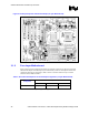
Figure 8. Six Layer Stack-Up
6-Layer_stackup
6 Layers
Layer 0
Layer 1Vcc Plane
Signal
Layer 2 Signal
Layer 3
Layer 4
Signal
Layer 5 Signal
Vss Plane