
Intel Pentium 4 Processor in the 478-pin Package / Intel 850 Chipset Platform Family Design Guide
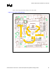

Platform Placement and Stack-Up Overview
R
38 Intel
®
Pentium
®
4 Processor / Intel
®
850 Chipset Family Platform Design Guide
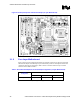
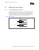
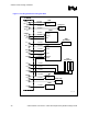
3.2.3 Four-Layer Motherboard Stack-Up
The following figure shows a 4-layer stack-up.
• If possible, signals should be referenced to a V
SS
plane.
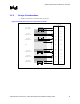
Figure 10. 4-Layer Intel
®
Pentium
®
4 Processor in the 478 Pin Package and Intel
®
850 Chipset Example Stack-Up for µATX Form Factor
Total Thickness: 62 mils
4.5 Mil Prepreg
Component Side Layer 1 ½ oz cu
~48 Mil Core
Gound Layer 3 1 oz cu
4.5 Mil Prepreg
Solder Side Layer 4 ½ oz cu
Power Plane Layer 2 1 oz cu
Design Considerations
Intel has found that the following recommendations aid in the design of an Intel Pentium 4
processor-based platform.
• Impedance requirements
60-ohm impedance ± 15% for AGP at 5mil trace width
50-ohm impedance ± 15% for the system bus at 7 mil trace width
28-ohm impedance ± 10% for the memory interface at 18 mil trace width
• Minimum via size is 12 mil finished in a 26 mil land with 35 mil antipad