
Intel Pentium 4 Processor in the 478-pin Package / Intel 850 Chipset Platform Family Design Guide

System Bus Routing
R
Intel
®
Pentium
®
4 Processor / Intel
®
850 Chipset Family Platform Design Guide 71
5.4 Routing Guidelines for Asynchronous GTL+ and
Other Signals
This section describes layout recommendations for signals other than data, strobe and address.
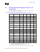
Table 13 lists the signals covered in this section.
Table 13. Miscellaneous Signals (Signals That Are Not Data, Address, or Strobe)
1,3
Signal Name Type Direction Topology Driven by Received
by
Notes
A20M# Asynchronous GTL+ I 2 ICH2 Processor
BR0# AGTL+ I/O 4 Processor 2
COMP[1:0] analog I 5 External
logic
Processor
FERR# Asynchronous GTL+ O 1a Processor ICH2 2
IGNNE# Asynchronous GTL+ I 2 ICH2 Processor
INIT# Asynchronous GTL+ I 2a ICH2 Processor
/FWH
2
LINT0/INTR
LINT1/NMI
Asynchronous GTL+ I 2 ICH2 Processor
PROCHOT# Asynchronous GTL+
OD
O 1b Processor External
logic
2
PWRGOOD Asynchronous GTL+
OD
I 2-b ICH2 Processor 2
RESET# AGTL+ OD I 4 MCH Processor 2
SLP# Asynchronous GTL+ I 2 ICH2 Processor
SMI# Asynchronous GTL+ I 2 ICH2 Processor
STPCLK# Asynchronous GTL+ I 2 ICH2 Processor
THERMTRIP# Asynchronous GTL+ O 1b Processor External
logic
2
VCCA power I 3 External
logic
Processor
VCCIOPLL power I 3 External
logic
Processor
VCC_SENSE other O Processor
VID[4:0] other O Processor V
REG
VSSA power I 3 Ground Processor
VSS_SENSE other O Processor
NOTES:
1. For more information on these signals, refer to Chapter 11.
2. All miscellaneous signals that require a pull up should be pulled up to VCC_CPU.
All signals must meet the AC and DC specifications as documented in the processor datasheet.