
Intel Pentium 4 Processor in the 478-pin Package / Intel 850 Chipset Platform Family Design Guide

System Bus Routing
R
Intel
®
Pentium
®
4 Processor / Intel
®
850 Chipset Family Platform Design Guide 73
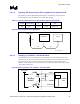
Table 15. Layout Recommendations for PROCHOT# and THERMTRIP# Signals (Topology 1b)
Trace Zo Trace Spacing L1 L2 L3 Rpu
60 Ω 7 mil 1–17” 10” max 3” max 62 Ω ±5%
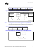
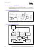
Figure 35. Routing Illustration for PROCHOT# and THERMTRIP# (Topology 1B)
Processor
Topo1b_PROCHOT_Route
R
PU
VDD CPU
Voltage
Translator
L1 L3
External Logic
L2
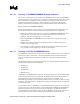
5.4.1.2 Topology 2: Asynchronous GTL+ Signals Driven by Intel
®
ICH2
These signals (A20M#, IGNNE#, LINT[1:0], SLP#, SMI#, and STPCLK#) should adhere to the
following routing and layout recommendations. Figure 36 illustrates the recommended topology.
Table 16. Layout Recommendations for Miscellaneous Signals (Topology 2)
Trace Zo Trace Spacing L1 Rpu
60 Ω 7 mil 12 inches max None
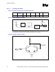
Figure 36. Routing Illustration for A20M#, IGNNE#, LINT[1:0], SLP#, SMI#, and STPCLK#
Processor
Topo2_Route
ICH2
L1