
Intel Pentium 4 Processor in the 478-Pin Package Thermal Design Guidelines

Intel
®
Pentium
®
4 Processor in the 478-Pin Package Thermal Design Guidelines
R
Design Guide 11
2 Thermal Mechanical Information
2.1 Mechanical Requirements
2.1.1 Processor Package
The Intel
®
Pentium
®
4 processor in the 478-pin package is packaged in a flip-chip pin grid array 2
(FC-PGA2) package technology. Please refer to the processor datasheet for detailed mechanical
specifications of the 478-pin package.
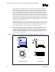
The package includes an integrated heat spreader (IHS). The IHS spreads the non-uniform heat
from the die to the top of the IHS, out of which the heat flux is more uniform and on a larger
surface area. This allows more efficient heat transfer out of the package to an attached cooling
device. The IHS is designed to be the interface for mounting a heatsink. Details can be found in
the processor datasheet.
The processor connects to the motherboard through a ZIF surface mount socket. A description of
the socket can be found in the Intel
®
Pentium
®
4 Processor, 478-Pin Socket (mPGA478B) Design
Guidelines.
The processor package has mechanical load limits that are specified in the datasheet. These load
limits should not be exceeded during heatsink installation, removal, mechanical stress testing, or
standard shipping conditions. For example, when a compressive static load is necessary to ensure
thermal performance of the thermal interface material between the heatsink base and the IHS, this
compressive static load should not exceed the compressive static load specification given in the
processor datasheet.
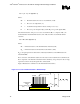
The heatsink mass can also add additional dynamic compressive load to the package during a
mechanical shock event. Amplification factors due to the impact force during shock have to be
taken into account in dynamic load calculations. The total combination of dynamic and static
compressive load should not then exceed the processor datasheet compressive dynamic load
specification during a vertical shock. For example, with a 1 lbm heatsink, an acceleration of 50 g
during a 11ms shock results approximately in a 100 lbf dynamic load on the processor package. If
a 100 lbf static load is also applied on the heatsink for thermal performance of the thermal
interface material and/or for mechanical reasons, the processor package sees 200 lbf. The
calculation for the thermal solution of interest should be compared to the processor datasheet
specification.
It is not recommended to use any portion of the substrate as a mechanical reference or load-
bearing surface in either static or dynamic compressive load conditions.