
Intel Pentium 4 Processor in the 478-Pin Package Thermal Design Guidelines

Intel
®
Pentium
®
4 Processor in the 478-Pin Package Thermal Design Guidelines
R
14 Design Guide
extruded heatsink may not be sufficient to cool the entire range of thermal design power. It is
expected that more advanced cooling techniques will be necessary.
In designing a cooling solution, the goal is to keep the processor within the operational thermal
specifications. Failure to do so will shorten the life of the processor and potentially cause erratic
system behavior.
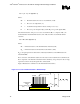
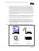
To remove the heat from the processor, three basic parameters have to be considered:
• The area of the surface on which the heat exchange takes place. Without any
enhancements, this is the surface of the IHS. One method used to improve thermal
performance is to increase the surface area of the IHS by attaching a heatsink to it. Heatsinks
extend the heat exchange surface through the use of fins that can be of various shapes, and are
attached to a heatsink base in contact with the IHS.
• The conduction path from the heat source to the heatsink fins. Providing a direct
conduction path from the heat source to the heatsink fins and selecting materials with higher
thermal conductivity typically improve heatsink performance. The length, thickness, and
conductivity of the conduction path from the heat source to the fins will directly impact the
thermal performance of the heatsink. In particular, the quality of the contact between the
package IHS and the heatsink base has higher impact on the overall cooling solution
performance as processor cooling requirements become more strict. Thermal interface
material (TIM) can be use to fill in the gap between the IHS and the bottom surface of the
heatsink, and thereby improve the overall performance of the stack-up (IHS-TIM-Heatsink).
Although, with extremely poor heatsink interface flatness or roughness, TIM may not
adequately fill the gap. The TIM thermal performance depends on its thermal conductivity as
well as the pressure load applied to it. Refer to Appendix A for further information regarding
managing the bond line between the IHS and the heatsink base.
• The heat transfer conditions on the surface on which heat transfer takes place.
Convective heat transfer occurs between the airflow and the surface exposed to the flow. It is
characterized by the local ambient temperature of the air and the local air velocity over the
surface. The higher the air velocity and turbulence over the surface, and the cooler the air, the
more efficient is the resulting cooling. In the case of a heatsink, the surface exposed to the
flow includes in particular the fin faces and the heatsink base.
Active heatsinks typically incorporate a fan that helps manage the airflow through the heatsink.
Passive heatsink solutions require an in-depth knowledge of the airflow in the chassis. Typically,
passive heatsinks may see lower air speed, and are therefore larger (and heavier) than active
heatsinks due to the increase in fin surface required to meet a required performance. As the
heatsink fin density (the number of fins in a given cross-section) increases, the resistance to the
airflow increases: it is more likely that the air travels around the heatsink instead of through it,
unless air bypass is carefully managed. Using air-ducting techniques to manage bypass are can be
an effective method for controlling airflow through the heatsink.