
Intel Pentium 4 Processor in the 478-Pin Package Thermal Design Guidelines

Intel
®
Pentium
®
4 Processor in the 478-Pin Package Thermal Design Guidelines
R
Design Guide 15
2.2.2.1.2 Thermal Interface Material
Thermal interface material application between the processor IHS and the heatsink base is
generally required to improve thermal conduction from the IHS to the heatsink. Many thermal
interface materials can be pre-applied to the heatsink base prior to shipment from the heatsink
supplier and allow direct heatsink attach, without the need for a separate thermal interface material
dispense or attach process in the final assembly factory.
All thermal interface materials should be sized and positioned on the heatsink base in a way that
ensures the entire processor IHS area is covered. It is important to compensate for heatsink-to-
processor attach positional alignment when selecting the proper thermal interface material size.
When pre-applied material is used, it is recommended to have a protective application tape over it.
This tape must be removed prior to heatsink installation.
2.2.2.1.3 Summary
In summary, considerations in heatsink design include:
• The local ambient temperature at the heatsink, the power being dissipated by the processor,
and the corresponding maximum T
C
at the processor frequency considered. These parameters
are usually combined in a single lump cooling performance parameter, Θ
CA
(case to air
thermal resistance). More information on the definition and the use of Θ
CA
is given Section
2.2.2.2 and Section 2.2.2.3.
• Heatsink interface (to IHS) surface characteristics, including flatness and roughness.
• The performance of the thermal interface material used between the heatsink and the IHS.
• Surface area of the heatsink.
• Heatsink material and technology.
• Volume of airflow over the heatsink surface area.
• Development of airflow entering and within the heatsink area.
• Physical volumetric constraints placed by the system.
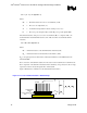
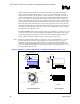
2.2.2.2 Characterizing Cooling Performance Requirements
The notion of “thermal resistance” is convenient to characterize the performance needed for the
cooling solution and to compare cooling solutions in identical situations. Be aware, however, of its
limitation when it comes to a real design. Heat transfer is a three-dimensional phenomenon that
can rarely be accurately and easily modeled by lump values.
The thermal resistance value from case-to-local ambient (Θ
CA
) is used as a measure of the thermal
performance of the overall cooling solution that is attached to the processor package. It is defined
by the following equation, and measured in units of °C/W: