
Intel Pentium 4 Processor in the 478-Pin Package Thermal Design Guidelines

Intel
®
Pentium
®
4 Processor in the 478-Pin Package Thermal Design Guidelines
R
Design Guide 17
2.2.2.3 Example
The cooling performance Θ
CA
is then defined using the notion of thermal resistance described
above:
• Define a target case temperature T
C,F
and corresponding thermal design power TDP
F
from
thermal specifications at a target frequency given in the processor datasheet.
• Define a target local ambient temperature around the processor, T
A
.
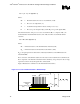
Since the processor thermal specifications (T
C
and TDP) can vary with the processor frequency, it
may be important to identify the worse case (smallest Θ
CA
) for a targeted chassis (characterized by
T
A
) to establish a design strategy such that a given heatsink can cover a given range of processor
frequencies.
The following provides an illustration of how one might determine the appropriate performance
targets. The power and temperature numbers used here are not related to any Intel processor
thermal specifications, and are just given to carry out the example.
Assume the datasheet TDP is 55W and the case temperature specification is 70 °C. Assume as
well that the system airflow has been designed such that the local ambient temperature is 45°C.
Then the following could be calculated using equation 1 from above:
Θ
CA
= (T
C,F
- T
A
) / TDP
F
= (70 – 45) / 55 = 0.45 °C/W
To determine the required heatsink performance, a heatsink solution provider would need to
determine Θ
CS
performance for the selected TIM and mechanical load configuration. If the
heatsink solution were designed to work with a TIM material performing at Θ
CS
≤0.15 °C/W,
solving for equation 2 from above, the performance of the heatsink would be:
Θ
SA
= Θ
CA
− Θ
CS
= 0.45 − 0.15 = 0.30 °C/W
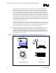
2.2.2.4 Looking at the Whole Thermal Solution
The heat generated by components within the chassis must be removed to provide an adequate
operating environment for both the processor and other system components. Moving air through
the chassis brings in air from the external ambient environment and transports the heat generated
by the processor and other system components out of the system. The number, size and relative
position of fans and vents have a decisive impact on the chassis thermal performance, and
therefore on the ambient temperature around the processor. The size and type (passive or active) of
the thermal cooling device and the amount of system airflow are related and can be traded off
against each other to meet specific system design constraints. Additional constraints are board
layout, spacing, component placement, and structural considerations that limit the thermal solution
size. For more information, refer to the Performance ATX Desktop System Thermal Design
Suggestions or Performance microATX Desktop System Thermal Design Suggestions documents
available on the http://www.formfactors.org/
web site.